
 WhatsApp: +86 16626708626
 Email:
  Phone: +86 16626708626
Description
Key Technical Specifications
| Parameter | Specification Value |
| Model / Part Number | PCI-6518 / 778964-01 |
| Manufacturer | National Instruments (NI) |
| Bus Interface | Universal PCI (3.3V and 5V signaling systems) |
| Digital Inputs | 32 Optically Isolated Inputs (Sinking/Sourcing) |
| Digital Outputs | 32 Optically Isolated Sourcing Outputs |
| Input Voltage Range | 0 to 30 VDC (24V Logic Level Compatible) |
| Output Voltage Range | 5 to 30 VDC (Requires external output bus supply) |
| Output Drive Current | Up to 350 mA per channel (sourcing) |
| Isolation Rating | 60 VDC continuous channel-to-bus bank isolation |
| Connector Type | Dual 37-Pin Male D-Sub Connectors (P1 and P2) |
| Supported Driver | NI-DAQmx |
Product Introduction
The NI PCI-6518 is an industrial 64-channel isolated digital input and output PCI card designed for factory automation, industrial switching, machine control, and process monitoring. Featuring 32 optocoupled digital inputs and 32 sourcing digital outputs, it safely bridges standard 24V industrial sensors, relays, solenoids, and actuators directly to host computer systems.
Built with 60 VDC bank-to-bank isolation, the PCI-6518 protects sensitive PCI bus circuitry from ground loops, high-voltage spikes, and electrical noise typical of harsh industrial environments. It incorporates programmable power-up states to ensure connected machinery remains safe during reboot, along with digital input filtering to eliminate contact bounce from mechanical switches.
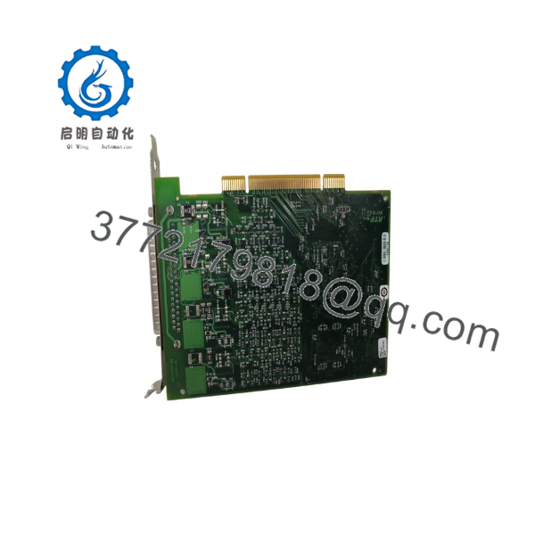
PCI-6518
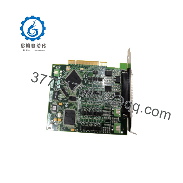
PCI-6518
Troubleshooting Quick Reference
| Symptom | Possible Cause | Relevance to this Part | Quick Check Method | Recommendation |
| Card Not Recognized in MAX | Unseated PCI card or missing driver software | ✅ High | Open NI Measurement & Automation Explorer (NI MAX) under “Devices & Interfaces”. | Re-seat card in the slot; ensure NI-DAQmx driver package (v8.0 or later) is properly installed. |
| Digital Outputs Not Switching | Missing external V_{CC} power supply on output port | ✅ High | Measure DC voltage across V_{CC} and V_{GND} pins on the 37-pin output header. | Supply external 5–30 VDC power to the output bank pins; isolated outputs cannot drive loads without bus power. |
| Inputs Unresponsive to 24V | Incorrect wiring topology (Sinking vs. Sourcing mismatch) | ✅ High | Verify input signal polarity relative to the V_{COM} common terminal pin. | Ensure external sensor loop wiring connects correctly between the input channel pin and V_{COM}. |
| Glitch / False Triggers on Input | Mechanical switch contact bounce or EMI noise | ❓ Medium | Inspect signal transition line with an oscilloscope or NI MAX task reader. | Enable NI-DAQmx programmable digital input filtering (software selectable from microsecond to millisecond ranges). |
| Output Driver Thermal Shutdown | Overcurrent load condition (>350 mA per channel) | ❓ Medium | Measure current draw per activated output line using a multimeter. | Install external relay modules (e.g., CB-37FH) if switching high-power inductive loads exceeding 350 mA. |
Frequently Asked Questions (FAQ)
Q: Does the PCI-6518 require external power to drive digital outputs?
A: Yes. The 32 digital outputs are optically isolated sourcing outputs. They require an external DC power supply (5 to 30 VDC) wired to the card’s external supply pins (V_{CC} and V_{GND}) on the 37-pin D-Sub connector.
Q: What is the main difference between sinking and sourcing outputs?
A: The PCI-6518 features sourcing outputs, meaning the module supplies current from the external positive voltage supply (V_{CC}) directly out to the load when activated.
Q: What cabling accessories are used to connect to the PCI-6518?
A: The board uses two 37-pin D-Sub connectors. Common accessories include two SH37F-37M shielded cables paired with two CB-37T or DIN-37TP terminal blocks.
Q: Can I set the startup state of the digital outputs?
A: Yes. The supports software-configurable power-up states via NI-DAQmx, ensuring outputs default to high, low, or tristate upon system boot to protect downstream hardware.
SOP Quality Control Process
- Inbound & Visual Inspection: Check gold PCI edge contacts for physical damage, verify 37-pin connector pins for alignment, and cross-reference factory serial tags (778964-01 / 191316C-01).
- PCI Recognition & Self-Test: Insert card into test chassis running NI MAX and execute hardware self-test diagnostics.
- High-Density Isolated Loopback Test: Connect all 32 inputs and 32 outputs to an external 24V industrial test fixture. Run full-channel bit pattern verification (0xAA, 0x55, shifting bits) at maximum rated switching frequencies.
- Isolation Check: Perform dielectric insulation check across isolated ground banks and computer host chassis ground.
- ESD Packaging: Apply anti-static treatment and seal card inside a vacuum ESD shielding bag with desiccant.
Technical Pitfall & Survival Guide
- ❗ Forgetting External Output Power (V_{CC}): A very common oversight is attempting to read output voltages without connecting external power to V_{CC} and V_{GND}. The outputs are optically isolated and do not draw operational power from the PCI bus.
- ❗ Inductive Kickback Hazard: When switching inductive loads (such as 24V solenoids or mechanical relays), ensure flyback diodes are installed across the load terminals to prevent high-voltage inductive spikes from damaging the internal sourcing transceivers.
- ❗ Connector Pin Cable Mismatch: The card utilizes 37-pin D-Sub female ports. Ensure you use male-to-female 37-pin straight-through cables (like the SH37F-37M) rather than null-modem or pin-swapped custom harnesses.



