WhatsApp: +86 16626708626
 Email:
 Phone: +86 16626708626
Description
Key Technical Specifications
NI identifies the PCI-8517 specifications as typical unless otherwise noted. The model-specific specification sheet takes precedence over older family-level summaries.
| Parameter | Value |
|---|---|
| Communication Protocol | FlexRay |
| Interface Count | 2 fully functional FlexRay interfaces; usable for separate networks |
| Physical-Layer Transceivers | NXP TJA1080 × 2 |
| Baud Rate | Minimum: 1 Mbit/s; maximum: 10 Mbit/s |
| Host Bus | Conventional PCI |
| Network Connectors | 2 × 9-pin male D-SUB; each connector includes FlexRay A and B signal pairs |
| Onboard Termination | Software-selectable: none or 80 Ω between BM and BP for both channels A and B |
| Synchronization | RTSI: 7 trigger lines and 1 clock line; 2 front-panel SMB synchronization connectors |
| Synchronization Electrical Characteristics | TTL; power-on state: input/high impedance; rising-edge triggers |
| PCI Supply Requirements | +5 V DC ±5%: 210 mA; +3.3 V DC ±5%: 940 mA |
| Isolation | Port-to-port ground and port-to-earth ground: 60 V DC continuous, Measurement Category I; 500 V RMS withstand test for 5 seconds |
| Physical and Environmental | 106.7 × 167.6 mm; 102 g; operating: 0–55 °C; 10–90% RH, noncondensing; indoor use |
Specifications come from NI’s model-specific documentation, product information, pinout, and NI-XNET family datasheet.
❗ Warning: Two ports do not mean one connector for FlexRay A and another for FlexRay B. Each network connector carries both A and B pairs. Use the FlexRay pinout—not an RS-232 or CAN cable assumption.
Product Introduction
The NI PCI-8517 is a two-port FlexRay interface card for ECU development, hardware-in-the-loop simulation, bus monitoring, and automated test systems. Its NI-XNET platform supports frame and signal communication at rates up to 10 Mbit/s.
Two fully functional interfaces can connect separate networks or support single-ECU testing when other cold-start nodes are unavailable. Integrated transceivers, software-selectable termination, and external synchronization reduce the additional interface hardware needed for a configured FlexRay test bench.
Troubleshooting Quick Reference
| Symptom | Possible Cause | Relevance to this Part | Quick Check Method | Recommendation |
|---|---|---|---|---|
| Card is absent from the host or NI configuration tools | Driver/OS incompatibility, poor PCI seating, or host fault | Hardware fault possible; not established | Check OS hardware enumeration and the installed NI-XNET readme for device/OS support; power down before inspecting seating | Confirm the software environment and PCI host before replacing |
| Card is detected but no frames appear | Wrong interface assignment, incorrect database, wiring fault, or inactive cluster | Configuration/network checks first | Verify selected interface, baud rate, database/cluster settings, and connector mapping; compare against a known-working setup | Do not replace a detected card solely because the network is silent |
| ECU does not enter normal communication | Startup configuration or missing cold-start participation | Cluster configuration directly relevant | Compare startup settings and participating nodes with the approved test configuration; capture startup/status information | Verify the intended two-interface cold-start arrangement |
| FlexRay A works but B does not | Missing B pair, cable fault, or incorrect channel configuration | Wiring/configuration first | With power removed, check continuity of A on pins 7/2 and B on pins 8/4; check reference ground on pin 3 | Correct the affected pair and channel configuration before replacement |
| Communication is intermittent | Incorrect termination, unsuitable cable, topology issue, or ground-reference problem | Physical layer directly relevant | Audit all external and onboard terminations; inspect the harness and compare with a short, known-good FlexRay connection | Correct topology and termination; do not add resistors blindly |
| Frames appear but signal values are wrong | Wrong database revision, frame mapping, or signal scaling | Usually software/database-related | Compare the active database and session configuration with the approved project; inspect raw frames alongside decoded signals | Restore the correct database before suspecting the transceiver |
| Bus communication works but synchronization fails | Wrong RTSI/SMB route, edge selection, cable, or signal level | Synchronization path requires isolation | Verify the selected route; measure the trigger at the intended connector using a suitable oscilloscope; confirm TTL and rising-edge requirements | Separate synchronization faults from FlexRay communication faults |
Checks use NI’s documented interface architecture, pinout, termination, database tools, and synchronization characteristics. They are diagnostic steps—not failure-rate claims.
If the issue remains, contact technical support with board-label photos, harness details, OS and NI-XNET versions, database revision, session settings, exact errors, and timestamped bus logs.
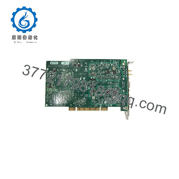
PCI-8517/2
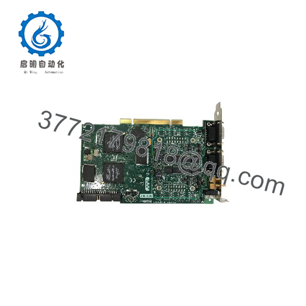
PCI-8517/2
Frequently Asked Questions (FAQ)
Is the PCI-8517/2 a CAN or LIN interface?
No. The PCI-8517/2 is a FlexRay interface. The NI-XNET family also includes CAN and LIN products, but a shared driver platform does not make their physical layers interchangeable.
Do not order a PCI-8512, PCI-8513, or PCI-8516 as an automatic replacement. Those models use different network physical layers. A similar D-SUB connector does not establish protocol or wiring compatibility.
The PXI-8517 is also not a physical drop-in replacement: it requires a PXI chassis rather than a conventional PCI host.
Can it communicate with one ECU without another cold-start node?
NI specifically identifies this capability: the PCI-8517 contains two fully functional FlexRay interfaces that allow an individual ECU to connect when other cold-start nodes are unavailable. The interfaces can also operate on two separate FlexRay networks.
That is a hardware capability, not a promise of automatic startup. Preserve the approved database, cluster timing, interface assignments, and startup configuration. For purchasing acceptance, require a demonstrated startup and frame exchange using the intended ECU or a representative test configuration.
Can I reuse a standard DB-9 cable? What termination does it need?
Only after verifying the cable’s actual pin mapping, shielding, and suitability for the network.
NI specifies the following FlexRay connections:
| Pin | Signal |
|---|---|
| 1 | No connection |
| 2 | FlexRay A BM |
| 3 | COM reference ground |
| 4 | FlexRay B BM |
| 5 | Shield |
| 6 | Optional COM reference ground |
| 7 | FlexRay A BP |
| 8 | FlexRay B BP |
| 9 | Optional external bus voltage |
These assignments come from NI’s FlexRay pinout. Do not apply an RS-232 or CAN wiring convention.
NI documents software-selectable termination of none or 80 Ω across BM/BP for both A and B. Audit external termination before enabling the onboard resistors. The family datasheet lists no required external bus power for the PCI/PXI-8517; COM provides the reference ground. Do not assume pin 9 requires a battery connection.
Can I hot-swap it, and will replacement preserve the application?
Plan a powered-down replacement. Put the test system in a safe state, isolate connected equipment as required, shut down and disconnect the host’s power, and use grounded ESD protection before handling the card.
Back up the host application, NI-XNET databases, interface aliases, session definitions, termination settings, and synchronization routes. NI documents host-side databases and project sessions as part of the NI-XNET configuration workflow; a replacement board alone does not restore those project files.
Record the working OS, NI-XNET version, application version, and board identification before removal. NI-XNET 21.0.1 explicitly lists PCI-8517 support, but that does not establish support in every newer release or OS combination. Check the exact release readme.
No specific firmware revision or DIP-switch configuration was supplied. Do not invent revision compatibility, node-address switches, or physical termination jumpers. NI documents software-selectable termination for this model.
What electrical limits and installation risks should I check?
Check both PCI supply rails: NI specifies 210 mA at +5 V and 940 mA at +3.3 V. Include other installed cards when checking the host’s per-slot and total power limits. A 20% planning allowance can provide capacity margin, but it does not replace the host manufacturer’s ratings.
The 60 V DC continuous isolation rating applies between port grounds and between port ground and earth. It is intended to prevent ground loops—not to permit 60 V on the FlexRay data pins. NI prohibits Measurement Category II, III, or IV connections.
Also keep front-panel synchronization within its documented TTL interface requirements. Do not connect a 24 V PLC trigger directly to an SMB synchronization input.
Is it obsolete, in stock, or available as new surplus? What warranty applies?
Current lifecycle classification and actual seller inventory have not been verified. NI lists ordering number 780685-02 and displayed an 8–9 week lead-time estimate when checked. That estimate is not a supplier stock guarantee or committed shipment date.
Before placing an order, require:
- Actual quantity, stock location, and committed dispatch date.
- Serial-linked board and connector photos.
- Full condition classification and repair/rework disclosure.
- Included cables, synchronization accessories, and software documentation.
- Functional-test records.
- Written warranty, exclusions, and return procedure.
Use “New Original / New Surplus” only when evidence supports unused OEM stock. Use “Factory Sealed” only if the original seal remains intact. Use “Refurbished (tested)” only when the seller documents refurbishment and testing. A lower price alone establishes neither authenticity nor condition.
What inspection and functional testing should the supplier document?
Request a serial-linked report covering the following sequence. No actual-unit inspection or test evidence was supplied.
- Inbound inspection and traceability
Review available OEM packing lists, purchase records, and applicable customs declarations. Cross-check labels and serial numbers. Inspect for corrosion, scratches, rework, discoloration, component damage, and damaged D-SUB or SMB connectors. Audit accessories and certificates. Verify security markings only where the production version actually used them. - Live functional testing
Identify the conventional PCI host, OS, NI-XNET version, test ECU or FlexRay peer, harness, termination configuration, and measurement instruments. Verify host detection and available self-test results. Exercise both interfaces with documented frame transmission and reception, known payloads, and required A/B connections. Test startup participation and synchronization where required. If acceptance requires a run exceeding 24 hours, record duration, bus configuration, error logs, and thermal conditions. A network ping is not a FlexRay functional test. - Electrical parameter testing
Use documented low-voltage checks appropriate to the board and fixture. Do not apply a blanket 500 V insulation-resistance test across data pins, synchronization connectors, or PCI contacts. NI’s 500 V RMS, five-second dielectric withstand specification applies to defined isolation barriers; it is not authorization for arbitrary field hipot testing. Require an applicable OEM-approved procedure before high-voltage testing. - Firmware and configuration verification
Record hardware identification, NI-XNET version, and any reported firmware information. Preserve the database revision, sessions, interface mapping, termination settings, and synchronization configuration. Photograph actual physical settings where present; do not substitute invented switch positions for software configuration. - Final QC and packaging
Require inspector sign-off, a dated report and QC label, ESD shielding packaging, cushioning, and a rigid corrugated box. Request serial-linked test photos and videos if available. State “verified functional under documented test conditions” only when the records support it.