
 WhatsApp: +86 16626708626
 Email:
  Phone: +86 16626708626
Description
3. Key Technical Specifications
| Parameter | Value |
|---|---|
| Ports | 2 (PXI-8423/2) or 4 (PXI-8423/4) |
| Interface | RS-485 / RS-422 (asynchronous) |
| Maximum Baud Rate | 460.8 kb/s |
| FIFO Buffer | 64 bytes per port |
| Isolation | Optical; 60 VDC continuous port-to-port and port-to-host; 2000 Vrms withstand (5 s) |
| ESD Protection (data lines) | ±15 kV (human body model) |
| Operating Voltage (RS-485) | –7 V to +12 V continuous |
| Power Requirement (+5 V from PXI backplane) | /2: 800 mA typical / 1.3 A max; /4: 1.0 A typical / 1.5 A max |
| I/O Connector | /2: DB-9 male; /4: 10-position modular jack (10P10C) |
| Dimensions | 100 × 160 mm (3.94 × 6.37 in.) |
| Maximum Cable Length (RS-485) | Up to 4,000 ft (typical multipoint) |
| Software Compatibility | NI-Serial driver; LabVIEW, LabWindows/CVI, Measurement Studio; Windows Plug-and-Play |
4. Product Introduction
The National Instruments PXI-8423 is an optically isolated RS-485/RS-422 serial interface module for 3U PXI chassis. It provides 2 or 4 independent ports for asynchronous serial communication with industrial instruments, PLCs, and multipoint networks.
Engineers select the PXI-8423 when galvanic isolation and multi-drop capability are required on a PXI backplane. Optical isolation (2000 Vrms withstand) protects the host system from ground loops and transients while the 64-byte FIFO and 460.8 kb/s rate support reliable data transfer. The module appears as standard COM ports under the NI-Serial driver, allowing existing applications to continue without rewrite.
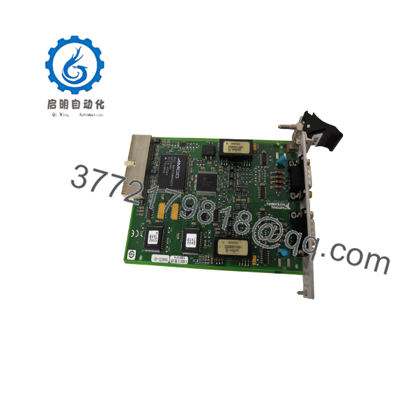
PXI-8423
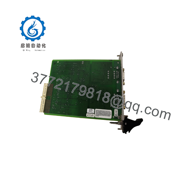
PXI-8423
5. Installation & Configuration Guide
Stage 1: Pre-Installation Preparation (≈5–10 min)
⚠️ Safety First: Notify operations of planned downtime. Place the PXI chassis in a safe state, lock out/tag out the power source, and wait at least 5 minutes for capacitors to discharge.
Tools Required: Grounded ESD wrist strap, PH1 screwdriver, digital multimeter, wire labels or markers, smartphone for photos.
Data Backup: Record the existing COM port assignments and baud/parity settings in NI Measurement & Automation Explorer (MAX). Photograph any terminal wiring or adapter cables. Export any application-specific serial configuration if present.
Stage 2: Removing the Old Module (≈5 min)
- Power down the chassis completely.
- Label and disconnect all serial cables or adapter cables from the front connectors. Do not force the modular jacks.
- Release the PXI injector/ejector handle and pull the module straight out to avoid bending backplane pins.
- Inspect the backplane connector for bent pins or debris.
⚠️ Keep the old module available for reference until the new unit is verified running.
Stage 3: Installing the New Module (≈10 min)
- Wear the ESD strap and verify the exact part number (777737-02 or 777737-04) matches the required port count.
- Configuration Clone (Critical): The PXI-8423 has no DIP switches for node address. Termination and bias resistors are external. Replicate the exact cable termination and bias network used on the previous installation. Take a photo of the old wiring before removal.
- Align the module with the PXI slot guides and insert firmly until the injector/ejector handle locks with an audible click.
- Reconnect the serial cables or 10P10C-to-DB-9 adapters. Torque screws only to the recommended value.
Self-Checklist: [ ] Part number confirmed [ ] Cables labeled and secured [ ] Injector handle locked [ ] ESD protection used.
Stage 4: Power-On & Testing (≈10–15 min)
Pre-Power Check: Use a multimeter to confirm no short exists on the +5 V rail relative to ground.
- Power up the PXI chassis only (leave field devices offline initially).
- Observe front-panel LEDs if present; the module should enumerate without red fault indicators.
- Open NI MAX, refresh devices, and confirm the new serial ports appear with the expected COM numbers.
- Verify the NI-Serial driver version and set port parameters (baud, parity, flow control) to match the field devices.
- Perform a loop-back or short-cable communication test before reconnecting the full multipoint network.
⚠️ Troubleshooting Note: If ports do not appear, reseat the module and check PXI Platform Services. Communication timeouts are most often caused by missing or incorrect termination/bias resistors or baud-rate mismatch. Solid red status usually indicates a power or backplane seating issue.
6. Frequently Asked Questions (FAQ)
Q: Can the PXI-8423 be hot-swapped under power?
No. PXI serial modules are not designed for hot-swap. Removing or inserting under power can damage the backplane connectors or the module itself. Always power down the chassis, wait for discharge, then swap.
Q: Is this model obsolete, and is stock genuinely new?
Yes, National Instruments has announced obsolescence for the 842x series. Available units are New Original (new surplus) or fully tested refurbished stock. Each unit is verified functional before shipment. Limited quantities remain; confirm availability at time of order.
Q: What is the direct replacement if stock is exhausted?
The functional successor family is the PXI-8431 (or PXIe-8431) series. The PXI-8431 offers higher baud rates and DMA performance. In many applications a PXI-8431 can replace a with driver-level recognition and minimal or no application changes, but verify pinout, isolation, and termination requirements against the current system.
Q: Will I lose my serial-port programming or COM assignments when I replace the module?
COM port numbers and application settings are stored in the host OS and NI-Serial driver configuration, not on the module itself. After installation, the new module typically enumerates with the same COM numbers if the slot and driver remain unchanged. Always document the existing settings in MAX before the swap.
Q: Why is the price lower than original NI list price?
These are New Surplus or carefully refurbished units from authorized secondary-market inventory. They carry the same form, fit, and function as original production parts and are fully tested, but they are not current-production factory-sealed modules from NI’s active catalog.
Q: Does the module require external termination and bias resistors?
Yes. RS-485 multipoint networks require proper termination (typically 100–120 Ω) at both ends of the bus and bias resistors on one node to keep the line in a known state when idle. Missing termination is the most common cause of intermittent communication after a module swap.
Q: What power draw should I allow for in the chassis budget?
Budget the maximum figures: 1.3 A (+5 V) for the 2-port version or 1.5 A for the 4-port version. Leave at least 20 % headroom on the chassis +5 V supply when multiple high-current modules share the same backplane.



