
 WhatsApp: +86 16626708626
 Email:
 Phone: +86 16626708626
Description
Core Product Summary
The National Instruments UMI-7764 is a Universal Motion Interface accessory designed to connect NI 7330, NI 7340, and NI 7350 motion controllers with third-party stepper and servo drives, encoder feedback devices, limit switches, and digital I/O. It supports up to four axes of simultaneous or independent motion control.
The interface provides separate terminal blocks for drive commands, encoder signals, limit and home switches, and auxiliary motion I/O. A single SH68-C68-S cable connects the UMI-7764 to the motion controller. An external +5 VDC supply is required to operate the encoder conversion circuitry and inhibit outputs. Its host-bus monitoring circuit also provides a drive-inhibit function when the host connection or monitored supply condition is lost.
Key Technical Specifications
| Parameter | Specification |
|---|---|
| Manufacturer | National Instruments (NI) |
| Model | UMI-7764 |
| Product type | Universal Motion Interface |
| Product category | Motion control connectivity accessory |
| Supported motion controllers | NI 7330, NI 7340, NI 7350 |
| Motion capacity | Up to 4 axes |
| Supported drives | Third-party stepper and servo drives |
| Stepper command interface | Step/Direction or CW/CCW |
| Servo command interface | ±10 V analog input at the drive |
| Encoder type | Incremental quadrature |
| Encoder input | Differential line driver or single-ended TTL/CMOS |
| Encoder voltage range | 0–5 VDC |
| Differential input threshold | ±0.3 V typical |
| Maximum quadrature frequency | 20 MHz |
| Encoder input filtering | 100 ns RC time constant |
| Limit/home input filtering | 10 µs RC time constant |
| Trigger input filtering | 100 ns RC time constant |
| Inhibit input voltage range | 0–12 VDC |
| Inhibit input pull-up resistor | 3.3 kΩ |
| Inhibit output voltage range | 0–5 VDC |
| External power supply | +5 VDC |
| Power consumption | 0.2 A plus user-defined encoder and limit power |
| Host bus interlock | 5 VDC ±5% |
| Motion controller connection | 68-pin interface |
| Required interface cable | SH68-C68-S |
| Dimensions | 195 × 152 × 45 mm |
| Operating temperature | 0 to 55 °C |
| Storage temperature | -20 to 70 °C |
| Relative humidity | 10–90%, noncondensing |
| Maximum operating altitude | 2,000 m |
Detailed Product Overview
Four-Axis Motion Interface Architecture
The NI UMI-7764 is designed to simplify the electrical connection between an NI motion controller and external drive equipment. Rather than connecting individual motor, encoder, and switch signals directly to the controller connector, the UMI-7764 distributes these signals through dedicated terminal blocks.
The interface supports up to four axes of simultaneous or independent motion control. Each axis has separate connections for:
- Amplifier and drive command signals.
- Incremental encoder feedback.
- Forward and reverse travel limits.
- Home reference switches.
- Drive inhibit signals.
- Distributed +5 VDC power.
This arrangement is useful when integrating third-party motion hardware into an NI-based control architecture. The motion controller remains responsible for motion commands and system-level configuration, while the UMI-7764 provides the field wiring interface.
Stepper and Servo Drive Integration
The UMI-7764 supports different command interfaces depending on the connected drive type.
For stepper systems, it provides Step/Direction signals or clockwise/counter-clockwise command signals. NI motion controllers can be configured to generate either command format.
For servo systems, the interface provides analog command signal connections. The servo amplifier must support the required ±10 V analog command interface.
The UMI-7764 does not replace the external drive amplifier. Motor power and drive-specific electrical requirements remain dependent on the connected amplifier and motor equipment.
Encoder Feedback and Signal Conditioning
Encoder feedback is an important part of closed-loop motion control. The UMI-7764 accepts incremental quadrature encoder signals through either differential line-driver or single-ended TTL/CMOS connections.
The encoder interface includes signal filtering to help reduce electrical noise. Differential line-driver encoders are recommended, particularly where encoder cable lengths exceed 10 feet.
For installation, twisted-pair conductors and an overall shield are recommended. The user guide specifies a minimum wire size of 24 AWG for encoder connections.
The encoder interface also supports Phase A, Phase B, and Index signals, allowing the connected motion controller to receive position feedback.
Host Bus Interlock and Drive Protection
One important feature of the UMI-7764 is its host bus monitoring and inhibit architecture.
The interface monitors the host-side +5 V supply to determine whether the motion controller remains powered and properly connected. If the monitored condition fails, the UMI-7764 asserts its inhibit outputs to disable the connected drives.
The inhibit logic also responds to the global Inhibit All signal, individual axis inhibit inputs, and motion-controller inhibit outputs.
This function provides an additional hardware-level drive-disable mechanism. It should not be interpreted as a substitute for a machine-specific safety circuit or safety-rated emergency-stop system.
Installation and Power Requirements
The UMI-7764 requires an external +5 VDC supply connected through its dedicated two-position power terminal block.
This supply powers the encoder conversion circuitry and inhibit output signals. It also distributes +5 VDC to the individual axis terminal blocks for compatible encoder and switch equipment.
The main connection to the motion controller uses the SH68-C68-S cable. Drive, encoder, and switch wiring should follow the electrical requirements of the corresponding third-party equipment.
During commissioning, signal verification should proceed through limit and home switches, encoder feedback, inhibit functions, and motion command connections.
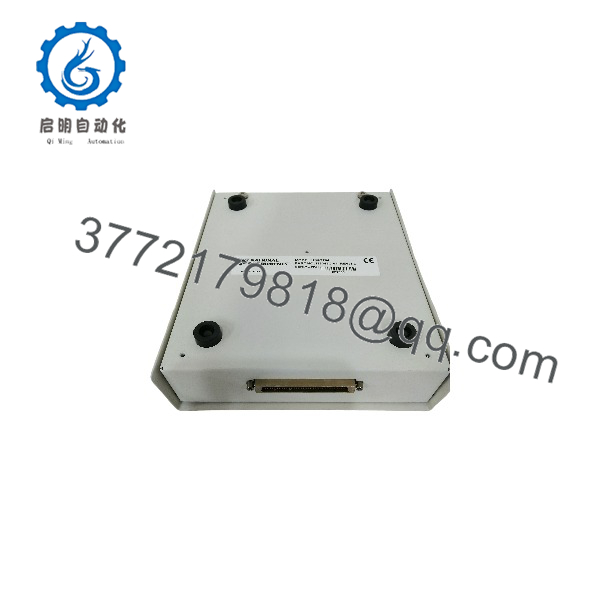
UMI-7764
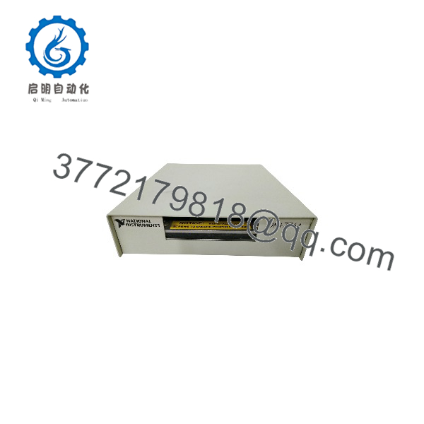
UMI-7764
System Compatibility & Integration Requirements
| Item / Dependency | Verified Compatibility or Requirement | Practical Note |
|---|---|---|
| Motion controller | NI 7330 | Supported controller |
| Motion controller | NI 7340 | Supported controller |
| Motion controller | NI 7350 | Supported controller |
| Controller interface cable | SH68-C68-S | Required connection cable |
| Drive equipment | Third-party stepper drives | Requires Step/Direction or CW/CCW interface |
| Drive equipment | Third-party servo drives | Requires ±10 V analog command input |
| Encoder | Differential line driver | Supported incremental encoder interface |
| Encoder | Single-ended TTL/CMOS | Supported encoder interface |
| External power | +5 VDC | Required for encoder circuitry and inhibit outputs |
| Software environment | NI motion software | Used with the associated motion controller |
| Digital I/O expansion | NI SCB-68 | Optional connection through an additional SH68-C68-S cable |
Important integration limitation: The UMI-7764 accessory specifications do not establish the complete motion-system performance limits. The connected motion controller and third-party drive specifications must also be considered.
Dimensions, Mounting & Connection Notes
Physical Dimensions
| Parameter | Value |
|---|---|
| Height | 45 mm |
| Width | 152 mm |
| Depth | 195 mm |
| Enclosure | Metal enclosure with hinged lid |
| Desktop installation | Attached rubber feet |
Connection Requirements
- Controller connection: 68-pin Motion I/O connector.
- Controller cable: SH68-C68-S.
- Power connection: Two-position +5 VDC/GND terminal block.
- Encoder connections: Separate terminal connections for Phase A, Phase B, and Index.
- Drive connections: Separate Step/Direction and analog command terminals.
- Limit connections: Forward limit, reverse limit, and home switch terminals.
Installation Precautions
- Connect the external +5 VDC supply before operating the interface.
- Confirm that the third-party drive command inputs match the selected signal configuration.
- Use shielded twisted-pair wiring for encoder signals.
- Check inhibit input and output polarity switch settings.
- Do not connect external signals to the NC terminal.
- Verify the drive, encoder, and limit-switch connections before enabling motion.
FAQ
1. What is the NI UMI-7764?
The NI UMI-7764 is a Universal Motion Interface accessory that connects NI motion controllers with external stepper drives, servo amplifiers, encoders, and motion-related I/O.
2. Which NI motion controllers support the UMI-7764?
The documented compatible controllers are NI 7330, NI 7340, and NI 7350.
3. How many axes does the UMI-7764 support?
It supports up to four axes of simultaneous or independent motion control.
4. Does the UMI-7764 require an external power supply?
Yes. It requires an external +5 VDC supply to operate its encoder conversion circuitry and inhibit outputs.
5. Which cable connects the UMI-7764 to the motion controller?
The specified controller interface cable is the NI SH68-C68-S.
6. What encoder types can the UMI-7764 accept?
It supports incremental quadrature encoders with differential line-driver or single-ended TTL/CMOS outputs.
7. Does the UMI-7764 support both servo and stepper drives?
Yes. It supports stepper drives using Step/Direction or CW/CCW commands and servo amplifiers using ±10 V analog command inputs.
8. What is the purpose of the host bus interlock?
The host bus interlock monitors the controller-side +5 V supply and activates the drive inhibit function if the monitored supply or connection condition fails.



