WhatsApp: +86 16626708626
 Email:
 Phone: +86 16626708626
Description
Core Product Summary (Brand / Model / Key Attributes)
The NI USB-6525 (Part Number: 779640-01) is a bus-powered, industrial digital I/O device from National Instruments (now part of Emerson) designed for data acquisition, industrial automation, and automated test applications. Housed in a compact, portable enclosure with removable screw-terminal blocks, it features eight channel-to-channel optically isolated digital inputs and eight channel-to-channel isolated solid-state relay (SSR) outputs, alongside a 32-bit event counter.
The USB-6525 operates over a full-speed USB 2.0 interface without requiring an external power supply. Its isolated digital inputs accept signal levels up to ±60 VDC, making it suitable for direct interface with 12V, 24V, and 48V industrial control logic. The normally open SSR outputs switch loads up to 60 VDC or 30 Vrms at 500 mA maximum current. Integrated software features include digital input filtering, change detection interrupts, programmable power-up output states, and a hardware watchdog timer to ensure safe operation in demanding control environments.
Key Technical Specifications
| Parameter | Specification |
| Model Number | NI USB-6525 (Part Number: 779640-01) |
| Manufacturer | National Instruments / Emerson |
| Bus Interface | USB 2.0 Full-Speed (Bus-Powered, Max 500 mA from USB) |
| Total Digital I/O Channels | 16 Channels (8 Inputs / 8 Outputs) |
| Digital Input Type | 8 Channel-to-Channel Optically Isolated Digital Inputs |
| Digital Input Voltage Range | ±60 VDC Channel-to-Channel |
| Input Logic Thresholds | Logic High: ≥ 3.2 VDC; Logic Low: ≤ 1.0 VDC |
| Digital Output Type | 8 Channel-to-Channel Isolated Solid-State Relays (SSR) |
| Output Switching Limits | Max 60 VDC / 30 Vrms, Max 500 mA Continuous |
| Event Counter | 1 × 32-Bit Counter (PFI 0 / Input Line 7) |
| On-Board Features | Digital Filtering, Change Detection, Watchdog Timer, Power-Up States |
| I/O Connectors | 2 × 16-Position Detachable Screw Terminal Blocks (16–28 AWG) |
| Operating Temperature | 0°C to 55°C |
| Physical Dimensions | 8.18 cm × 8.51 cm × 2.31 cm (With Connectors) |
Detailed Product Overview
The National Instruments USB-6525 delivers galvanic signal isolation for industrial monitoring and control setups where ground loops, electrical noise, and high voltage transients are present. By providing channel-to-channel optical isolation across both input and output banks, the device protects host PCs and connected USB hubs from field-side voltage spikes up to 60 VDC.
The eight digital input channels accommodate bipolar DC signals ranging from -60 VDC to +60 VDC. Each input circuit includes current-limiting electronics and optocouplers designed to sense standard industrial control voltages (such as 12V, 24V, or 48V logic) as well as traditional TTL levels. Configurable digital filtering suppresses high-frequency noise and mechanical contact bounce, while hardware change detection generates software interrupts only when state transitions occur, reducing CPU polling overhead.
The eight solid-state relay outputs act as SPST (Form A) normally open switches. SSR outputs eliminate mechanical wear, contact chatter, and arcing associated with electromechanical relays, enabling rapid switching of small solenoid valves, indicators, alarm horns, and actuator relay coils. The inclusion of programmable power-up output states allows engineers to define default safe conditions (open or closed) for all SSR channels upon initial power application before software execution begins.
System setup and control are managed using the NI-DAQmx driver framework, allowing integration with NI LabVIEW, C/C++, C#, Visual Basic .NET, and Python application software.
Engineering Selection Highlights
- Complete Channel-to-Channel Isolation → Optically isolates each individual DI and SSR channel up to ±60 VDC, preventing ground loops and protecting host controllers in noisy industrial settings.
- Industrial Voltage Level Support → Accepts input voltages up to ±60 VDC and switches up to 60 VDC / 30 Vrms, eliminating the need for external signal conditioning modules for standard 24V logic.
- Bus-Powered USB Operation → Powered entirely via the USB 2.0 bus, removing the requirement for an external AC/DC power adapter in field diagnostic and portable test setups.
- Integrated Hardware Watchdog & Power-Up States → Configurable hardware watchdog monitors application responsiveness and drives outputs to predefined safe states if host communication fails.
- On-Board Event Counter → Input line P1.7/PFI 0 doubles as a 32-bit hardware event counter for tallying pulse streams, flow meter outputs, or optical encoder pulses up to 5 kHz.
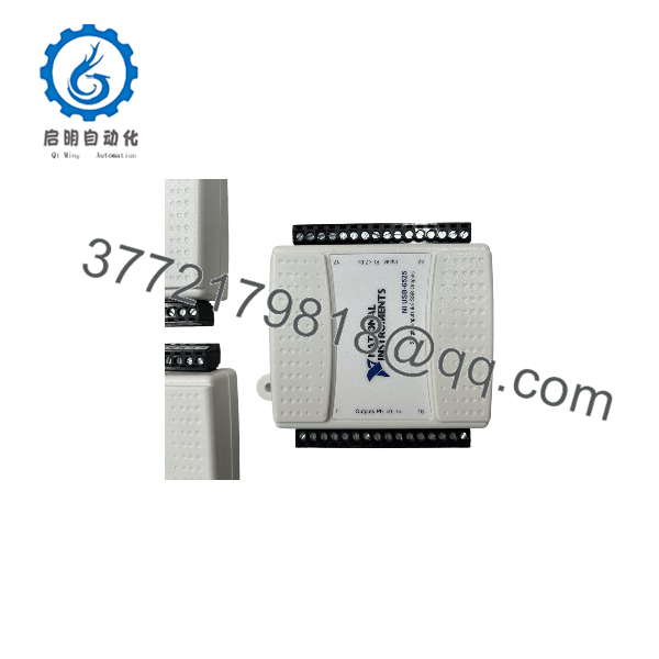
USB-6525
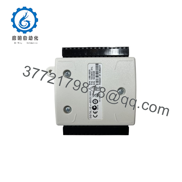
USB-6525
System Compatibility & Integration Requirements
| Item / Dependency | Verified Compatibility or Requirement | Practical Note |
| Software Driver | NI-DAQmx Driver Software | Requires compatible NI-DAQmx installation on host OS (Windows/Linux). |
| Programming Languages | LabVIEW, ANSI C, C#, VB.NET, Python | Programmed via standard NI-DAQmx API function calls and task execution. |
| USB Interface | USB 2.0 or USB 3.0 Type-A Host Port | Requires high-power USB port capable of supplying 500 mA at 5 VDC. |
| Field Wiring | 16 AWG to 28 AWG Wire | Connects to two included 16-position detachable screw terminal headers. |
| Inductive Load Protection | Flyback / Flywheel Diodes | Inductive DC loads connected across SSR outputs require external reverse flyback diodes to prevent voltage inductive kickback damage. |
Dimensions, Mounting & Connection Notes
- Dimensions: Measures 8.18 cm × 8.51 cm × 2.31 cm (3.22 in. × 3.35 in. × 0.91 in.) with terminal blocks installed; weight is approximately 87 g (3.1 oz).
- Mounting Options: Desktop placement default. Optional DIN-rail mounting kits or panel-mount strain relief accessories can be fitted.
- Wiring Terminals: Dual 16-position detachable screw terminal headers with a recommended terminal screw torque of 0.22 to 0.25 N·m (2.0 to 2.2 lb·in.).
- Cable Strain Relief: Built-in strain relief slot for securing the USB cable using standard zip ties to prevent accidental cable disconnection during operation.
FAQ
What is the NI USB-6525?
The NI USB-6525 is a bus-powered USB data acquisition device providing 8 isolated digital inputs, 8 solid-state relay outputs, and a 32-bit counter.
Does the USB-6525 require an external power supply?
No, the device is completely bus-powered via the host USB connection and draws up to 500 mA at 5 VDC.
What input voltage range is supported by the USB-6525 digital inputs?
The digital inputs support a continuous bipolar voltage range of -60 VDC to +60 VDC with channel-to-channel isolation.
What are the maximum switching capabilities of the SSR outputs?
The solid-state relay outputs can switch up to 60 VDC or 30 Vrms with a maximum continuous current of 500 mA per channel.
Can the USB-6525 count external digital pulses?
Yes, digital input line P1.7 / PFI 0 can be configured as a 32-bit hardware event counter.
What software drivers are required to operate the device?
The device requires National Instruments NI-DAQmx driver software, which provides programming interfaces for LabVIEW, C/C++, C#, and Python.
Verification & Troubleshooting Notes
Inductive Load Flyback Protection
When switching inductive loads (such as relay coils, solenoids, or motors) with the SSR outputs, always install an external flyback diode across the load. High inductive voltage spikes generated during switch-off can degrade or permanently damage solid-state relay outputs.
1.Verify Device Recognition in NI MAX:Software check.
Open Measurement & Automation Explorer (NI MAX) on the host computer and expand the “Devices and Interfaces” tree.
Verification: The USB-6525 appears under connected devices without exclamation mark warning icons, and the self-test diagnostic tool passes successfully.
2.Perform Digital I/O Test Panel Verification:Signal check.
Open the Interactive Test Panel for the USB-6525 within NI MAX. Toggle SSR output states manually and monitor input channel state changes.
Verification: Physical SSR outputs switch loads as commanded, and applied input voltages (≥ 3.2 VDC) register clearly as logic High state on the indicator lamps.
3.Check USB Port Power & Terminal Connections:Wiring & power check.
If the device LED fails to illuminate or disconnects intermittently, verify the unit is connected directly to a powered USB host port rather than an unpowered USB hub.
Verification: The green ACTIVE/POWER LED on the top panel illuminates steadily.