
 WhatsApp: +86 16626708626
 Email:
  Phone: +86 16626708626
Description
Key Technical Specifications
| Parameter | Specification / Value |
| Manufacturer | NK Technologies |
| Part Number | AG1-SDT1-24U-DEN-A55 |
| Product Series | AG Series Ground Fault Detectors |
| Power Supply Voltage | 24 V AC/DC (Nominal) |
| Setpoint / Trip Level | Factory set 55 mA |
| Reset Mode | Automatic reset (Auto-Reset) |
| Output Contacts | Single Pole Double Throw (SPDT) Relay / Form C |
| Contact Mode | Normally De-Energized (DEN) |
| Aperture Diameter | 0.75 in (19 mm) solid-core window |
| Response / Delay Time | Built-in noise immunity with 150 ms added delay |
| Contact Rating | 1 A @ 120 V AC / 2 A @ 30 V DC |
| Enclosure Rating | Top terminal connection, UL 94V-0 flammability housing |
Product Introduction & Supply Chain Strategy
The NK Technologies AG1-SDT1-24U-DEN-A55 is a precision zero-sum ground fault sensor designed to continuously monitor current leakage in grounded single-phase and three-phase power distribution systems. Featuring a factory-calibrated 55 mA trip setpoint, 24 V AC/DC operating power, and a normally de-energized SPDT output, this unit provides immediate fault signaling and shunt trip activation in noise-sensitive industrial environments.
Procuring this sensor as New Surplus provides a high-reliability, cost-effective solution for facility managers and system integrators. Ground fault protection is a critical safety barrier; relying on salvaged or reconditioned sensing devices risks undetected leakage currents, nuisance tripping, or contact failure. Maintaining unused OEM surplus stock on-site eliminates lead times during emergency maintenance while ensuring full compliance with equipment safety standards at a lower Total Cost of Ownership (TCO).
Installation & Configuration Guide
1.Pre-Installation & Safety Preparation:Disconnect control power and field lines before wiring.
- De-energize all primary load wires passing through the sensor aperture and disconnect the 24 V AC/DC control power.
- Put on a grounded ESD wrist strap to protect internal solid-state measurement circuits from electrostatic discharge.
- Verify that all phase conductors and the neutral conductor (if present) pass through the 0.75 in aperture, ensuring the ground wire passes outside the sensor window.
2.Mechanical Mounting & Cable Routing:
- Secure the sensor housing to a flat panel or DIN rail mounting bracket inside the control enclosure.
- Route all current-carrying conductors neatly through the center of the aperture without putting mechanical tension on the sensor enclosure.
- Ensure no ungrounded shield wires or metallic conduit sleeves enter the sensor window.
3.Electrical Terminal Connections:
- Connect the 24 V AC or 24 V DC auxiliary supply leads to the designated supply terminals on the top terminal block.
- Wire the SPDT relay output terminals (Common, NO, NC) to your PLC digital input, alarm horn, or shunt-trip breaker circuit.
- Verify wire strip lengths and torque terminal screws to the manufacturer’s recommended specification.
4.Power-On & Functional Testing:
- Apply 24 V control power and verify that the power supply rails measure within allowable voltage tolerances (18–28 V AC/DC).
- Inject a controlled test current exceeding 55 mA through the aperture to verify relay actuation and output contact closure.
- Remove the test fault current to confirm automatic reset of the output contacts.
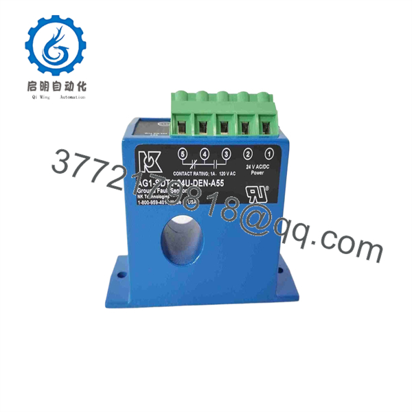
AG1-SDT1-24U-DEN-A55
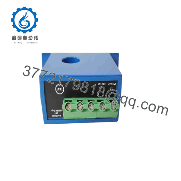
AG1-SDT1-24U-DEN-A55
Firmware/Software Versions & Upgrade Notes
- Hardware-Based Operation: The AG1-SDT1-24U-DEN-A55 operates entirely via analog sensing hardware and solid-state timing logic; it does not utilize programmable software or field-upgradable firmware.
- Factory Setpoint Integrity: The 55 mA setpoint and 150 ms noise-immunity delay are factory calibrated. Field adjustment of internal potentiometers is not supported and will void factory calibration accuracy.
- Noise Immunity Features: The “DEN” suffix designates a normally de-energized contact configuration with built-in EMI/RFI noise filtering. If replacing an “ENE” (normally energized) model, confirm your control logic setup before energizing to prevent inverted alarm states.
Frequently Asked Questions (FAQ)
What does “DEN” mean in the AG1-SDT1-24U-DEN-A55 part number?
“DEN” stands for Normally De-Energized contact operation. In this mode, the output relay remains unpowered during normal fault-free operation and energizes only when a ground fault exceeding 55 mA is detected.
Is this unit an authentic NK Technologies factory-new item or a used part?
This module is New Surplus (Original New). It is clean, unused inventory sourced from authorized distribution overstock or system integration projects. It has never been installed in a working panel or pulled from a decommissioned facility.
Can I adjust the ground fault trip level on this sensor?
No. The “-A55” suffix indicates a factory-calibrated fixed setpoint of 55 mA. If your application requires variable trip thresholds, you would need an adjustable model from the NK AG3 series instead.
Why should I choose New Surplus over a cheaper refurbished ground fault relay?
Ground fault relays are life-safety and equipment protection devices. Used or refurbished relays often suffer from degraded internal sensing transformers, dried-out filtering capacitors, or worn relay contacts. Buying New Surplus guarantees OEM component longevity and reliable tripping performance without paying full list price.
What is the purpose of the 150 ms delay option on this model?
The built-in 150 ms response delay provides noise immunity against transient current surges, motor startup spikes, and high electromagnetic interference (EMI/RFI). This prevents nuisance tripping while maintaining reliable ground fault protection.



