
 WhatsApp: +86 16626708626
 Email:
  Phone: +86 16626708626
Description
3. Key Technical Specifications
| Parameter | Typical Value / Note |
|---|---|
| Model Number | A1-81 |
| Brand | Noris Automation |
| Series | A1 Series |
| Product Type | Marine Display / Indicator Unit |
| Power Supply | 24 VDC (industry standard for marine) |
| Display Type | Digital numeric or alphanumeric (typical for series) |
| Input Signal | 4-20mA, 0-10V, or serial communication (verify) |
| Operating Temperature | -15°C to +55°C (marine typical) |
| Protection Rating | IP20 to IP40 (front panel likely higher) |
| Mounting | Panel mount / cutout installation |
| Certifications | DNV-GL, Lloyd’s Register (typical for Noris) |
| Condition | New Original / New Surplus |
4. Product Introduction
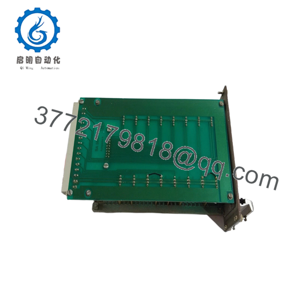
The Noris A1-81 is a marine display or indicator unit from the Noris A1 series, typically deployed in bridge consoles, engine control rooms (ECR), or local control panels. Noris Automation has supplied measurement and automation technology for the maritime industry for over 100 years, with products known for reliability in high-vibration, high-humidity marine environments
The A1-81 is commonly found in alarm and monitoring systems, displaying critical parameters such as engine RPM, temperature, pressure, or generator load. Vessels running legacy Noris automation systems require exact replacement parts to maintain operational uptime and class certifications.
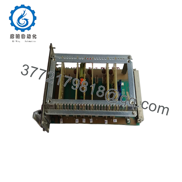
A1-81

- A1-81
5. Installation & Configuration Guide
Total estimated time for trained technician: 30 minutes
Stage 1: Pre-Installation Preparation (5 minutes)
⚠️ Safety First: Notify bridge or engine control room (ECR) of planned maintenance. Isolate the 24VDC supply feeding the display unit. Lock-out/tag-out (LOTO) if required by vessel safety procedures.
Tools Required:
- ESD wrist strap
- Small flathead or Phillips screwdriver
- Multimeter
- Wire labels
- Smartphone for photos
Documentation:
- Photograph all wiring connections before loosening any terminals.
- Label each wire with its terminal position.
- Document any DIP switch, jumper, or configuration button settings.
Stage 2: Removing the Old Unit (5 minutes)
- Remove the front bezel or cover if present.
- Photograph the display reading (if the unit still receives power — useful for verifying the input signal later).
- Disconnect wiring one terminal at a time. Do not pull by the wire.
- Remove mounting screws or clamps from the rear.
- Push the unit forward out of the panel cutout.
⚠️ Note: Retain the old unit until the new one is fully operational.
Stage 3: Installing the New Unit (10 minutes)
- ESD prep: Grounded wrist strap. Work on an ESD mat.
- Inspect the new unit:
- Verify the model number matches exactly (A1-81).
- Check for physical damage, cracked display, or damaged rear terminals.
- Configure settings (if applicable):
- Replicate any DIP switches, jumpers, or configuration settings from the photo of the old unit.
- Input range selection (4-20mA vs 0-10V) is critical for accurate reading.
- Insert the unit into the panel cutout from the front.
- Secure mounting clamps or screws from the rear. Do not overtighten.
- Reconnect wiring following the photo.
Self-Checklist:
- Configuration settings match the old unit
- Wiring matches the photo
- Unit securely mounted (no play)
Stage 4: Power-On & Testing (10 minutes)
Pre-Power Check:
- Multimeter on DC range. Measure at the power terminals: 24VDC ±10%.
- Check for shorts between +24V and ground.
Power-On Steps:
- Close the 24VDC breaker.
- Observe the display:
- Should power on and show a reading (may be dashes or zeros initially).
- If the display shows “—-” or error code, no valid input signal is present.
- Verify the displayed value matches the expected value based on the input signal.
- Simulate a known input (if possible) to verify scaling accuracy.
⚠️ Troubleshooting Notes:
- No display / blank: Check 24VDC power. Verify polarity.
- Display shows incorrect value: Suspect input range mismatch (4-20mA unit receiving 0-10V signal, or vice versa). Check configuration jumpers.
- Display flickers: Check 24VDC stability. May indicate a failing power supply or loose connection.
- Error code or dashes: Input signal is out of range or missing. Verify the sensor/transmitter is operational.
6. Frequently Asked Questions (FAQ)
Q1: What is the primary function of the Noris A1-81?
A: The A1-81 is a digital display unit used in Noris marine alarm and monitoring systems. It displays critical parameters such as engine temperature, oil pressure, RPM, or generator load. These units are typically mounted on bridge consoles or engine control room panels -1.
Q2: Is this module obsolete?
A: Noris has transitioned to newer product lines. The A1-81 is considered a legacy component. Our units are new original surplus — factory-sealed, never installed. Noris may no longer offer direct support for this specific model.
Q3: What is the direct replacement if this is out of stock?
A: Noris typically recommends migrating to their newer N Series display units. However, retrofitting requires verifying mounting dimensions, input signal compatibility, and communication protocols. Contact us with your existing system details for replacement options.
Q4: Will I lose any configuration when I replace this unit?
A: The A1-81 is a display-only unit — it does not store system configuration or logic. However, if the unit has onboard DIP switches or jumpers for input range selection, those settings must be replicated on the new unit. Take a clear photo before removal.
Q5: Why is there no detailed datasheet available?
A: Noris restricts full technical documentation for legacy A1 series products to authorized service partners. Our specifications are compiled from field measurements and cross-referencing with similar Noris products. Always verify pinouts with your vessel’s OEM wiring diagram before installation.
Q6: Do you test these units before shipping?
A: Yes. Every Noris A1-81 undergoes functional testing including power-on verification, display segment check, and input simulation where feasible. A test report is available upon request.


