
 WhatsApp: +86 16626708626
 Email:
  Phone: +86 16626708626
Description
3. Key Technical Specifications
| Parameter | Typical Value / Note |
|---|---|
| Model Number | Berg 061317 |
| Brand | Noris Automation |
| Series | Berg |
| Product Type | Marine Automation Module |
| Power Supply | 24 VDC (industry standard) |
| Operating Temperature | -15°C to +55°C (marine typical) |
| Protection Rating | IP20 (likely) |
| Mounting | DIN rail or backplane |
| Certifications | DNV-GL, Lloyd’s Register (typical for Noris) |
| Condition | New Original / New Surplus |
4. Product Introduction
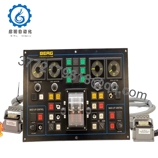
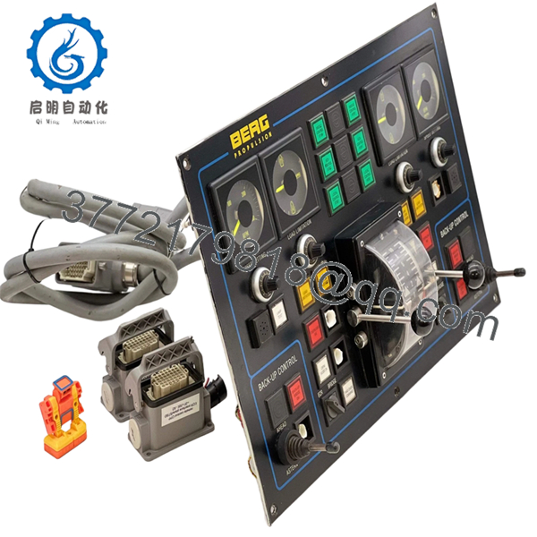
The Noris Berg 061317 is a marine automation component from the Noris Berg series, typically deployed in engine room monitoring and control systems (EMS). Noris Automation is recognized for ruggedized I/O and communication modules designed for the high-vibration, humidity, and temperature extremes found in commercial vessels.
Field experience indicates Berg series modules are often found interfacing with main engines, auxiliary generators, and alarm monitoring panels. This unit, 061317, serves as a specific variant within that series. Legacy vessels running Noris systems require exact replacement parts to maintain class certifications and operational uptime.

- Berg 061317
- Berg 061317
5. Installation & Configuration Guide
Total estimated time for trained technician: 20-30 minutes
Stage 1: Pre-Installation Preparation (5 minutes)
⚠️ Safety First: Notify engine control room (ECR) of planned maintenance. Isolate the 24VDC supply to the specific rack. Lock-out/tag-out (LOTO) if required by vessel safety procedures. Wait 2 minutes for capacitors to discharge.
Tools Required:
- ESD wrist strap
- Small flathead or Phillips screwdriver (verify fit on terminal blocks)
- Multimeter
- Wire labels
- Smartphone for photos
Documentation:
- Photograph all wiring connections before loosening any terminals.
- Label each wire with its terminal position.
- Note the slot position in the rack.
- Document any DIP switch or jumper settings.
Stage 2: Removing the Old Module (5 minutes)
- Remove the front cover if present.
- Photograph the LED status (if the unit still receives power).
- Disconnect wiring one terminal at a time. Do not pull by the wire — loosen the screw first.
- Release DIN rail locking clip or backplane latches.
- Pull the module straight out.
⚠️ Note: Retain the old module until the new one is fully operational.
Stage 3: Installing the New Module (8 minutes)
- ESD prep: Grounded wrist strap. Work on an ESD mat.
- Inspect the new unit:
- Verify the model number matches exactly (Berg 061317).
- Check for physical damage, bent pins, or corrosion.
- Clone Configuration (Crucial):
- Replicate all DIP switches and jumpers exactly as shown in the photo of the old unit.
- Node address and baud rate settings are critical for fieldbus communication.
- Mount the module:
- For DIN rail: Tilt the top in first, then push the bottom until the clip clicks.
- For backplane: Align card guides and push evenly until latches engage.
- Reconnect wiring following the photo. Torque terminal screws appropriately.
Self-Checklist:
- DIP switches/jumpers match the old unit
- Wiring matches the photo
- Module fully seated and locked
- No stray wire strands outside terminals
Stage 4: Power-On & Testing (7 minutes)
Pre-Power Check:
- Multimeter on DC range. Measure at the power terminals: 24VDC ±10%.
- Check for shorts between +24V and ground.
Power-On Steps:
- Close the 24VDC breaker.
- Observe LEDs:
- Green PWR LED = power OK
- Green RUN/ACT LED = communication active
- Red ERR LED = fault or configuration error
- Verify communication with the main controller (check the master CPU for “Module Online” status).
- Test discrete inputs by toggling the corresponding field sensors/switches.
- Monitor analog inputs for correct signal scaling.
⚠️ Troubleshooting Notes:
- Red ERR LED solid: Suspect a node address conflict or baud rate mismatch. Verify settings against the old module.
- No communication: Check fieldbus termination resistors. Measure bus voltage (typically 2-5V on RS-485 networks).
- Incorrect analog readings: Verify the input range (4-20mA vs 0-10V) matches the sensor configuration.
6. Frequently Asked Questions (FAQ)
Q1: Can I hot-swap this module while the system is powered?
A: Not recommended. Noris Berg series modules generally do not support hot-swap. Always isolate the 24VDC supply before removal or insertion. Hot-swapping can cause arcing, damage the backplane, or corrupt the fieldbus network.
Q2: Is this module obsolete?
A: Noris has transitioned focus to newer series. The Berg 061317 is considered legacy stock. Our units are new original surplus — factory-sealed, never installed. Noris likely no longer offers direct support for this specific model.
Q3: What is the direct replacement if this is out of stock?
A: Identifying a direct replacement requires the original I/O layout and communication protocol. Noris often recommends migrating to their newer N3000 or N5000 series equivalents, but this typically requires a rack adapter or complete system upgrade. Contact us with your existing system architecture for retrofit options.
Q4: Will I lose my programming logic when I replace this module?
A: No. The Berg 061317 is a remote I/O or communication module, not the main CPU. The logic resides in the central controller. However, if this module handles specific field devices, those devices will lose control during the swap. Plan for brief process interruption.
Q5: Why is there no detailed datasheet available?
A: Noris typically restricts full technical documentation to authorized service partners. Our specifications are compiled from field measurements, maintenance logs, and cross-referencing with similar Berg series units. Always verify pinouts with your vessel’s OEM wiring diagram before installation.
Q6: Do you test these units before shipping?
A: Yes. Every Noris Berg 061317 undergoes functional testing including power-on verification, communication loopback, and a 2-hour burn-in where feasible. A test report is available upon request.


