
 WhatsApp: +86 16626708626
 Email:
  Phone: +86 16626708626
Description
Key Technical Specifications
| Parameter | Value |
| Measuring Principle | Magnetic-inductive (contactless) |
| Output Signal | 4–20 mA (Standard current loop) |
| Supply Voltage | 18–32 V DC (Nominal 24 V DC) |
| Thread Size | M18 x 1.5 |
| Measuring Range | Dependent on pulse wheel (Adjustable via internal scaling) |
| Scanning Distance | 0.5 mm to 2.5 mm (Typical) |
| Material | Stainless Steel (V4A) / Marine-grade brass |
| Protection Class | IP67 / IP68 |
| Connection | Integrated plug or cable tail (G-type variant) |
Product Introduction & Supply Chain Strategy
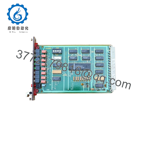
The Noris SA372-13G is a high-performance, magnetic-inductive speed sensor designed for the rigorous demands of marine engine and turbine monitoring. Unlike passive sensors, the SA372-13G features an integrated signal converter that transforms frequency pulses directly into a stabilized 4–20 mA analog output. This allows for long-distance signal transmission to a PLC or the Norimos 2000 system without the interference risks associated with raw pulse signals.
From a supply chain perspective, the SA372-13G is a critical “insurance” spare. Speed sensors are wear-and-tear items frequently exposed to extreme vibration and thermal cycling. Choosing a “New Surplus” unit over a refurbished one is vital for this specific component; refurbished sensors often suffer from microscopic insulation breakdown in the internal windings, leading to signal drift at high temperatures. By maintaining a New Surplus buffer stock, you ensure immediate replacement availability, preventing costly engine overspeed trips or emergency propulsion shutdowns.

- SA372-13G
- SA372-13G
Installation & Configuration Guide
Stage 1: Pre-Installation (Prep & Safety)
- Safety: Ensure the engine or rotating machinery is at a complete standstill and locked out.
- Cleaning: Inspect the scanning gear (pole wheel). Ensure it is free of metallic debris or oil sludge that could cause false readings.
- Tools: Have a 24 mm open-end wrench and a feeler gauge ready for gap setting.
Stage 2: Removal
- Disconnect the electrical cable/plug.
- Loosen the lock nut and unscrew the old sensor. Note the number of turns or use a depth gauge to estimate the previous gap setting.
Stage 3: Installation (Clone & Seat)
- Screw in the SA372-13G until it lightly touches the top of a gear tooth.
- Back the sensor off by the manufacturer-specified distance (typically 1.0 mm to 1.5 mm) using a feeler gauge.
- Tighten the lock nut firmly to prevent vibration-induced loosening.
Stage 4: Power-On & Testing
- Power the 24 V DC loop. Use a multimeter to verify the “base” current (approx. 4 mA when stationary).
- Start the machinery and verify the analog output scales linearly with RPM on the control system display.
Firmware/Software Versions & Upgrade Notes
- Hardware Scaling: The SA372-13G is often factory-scaled for a specific frequency range (e.g., 0–5000 Hz = 4–20 mA). Verify the “G” suffix configuration to ensure the measuring range matches your engine’s maximum RPM and tooth count.
- Calibration: This is an analog-out device; ensure the receiving PLC input card is calibrated to the same 4–20 mA range to avoid scaling errors in the tachometer readings.
- No Software Required: As a field device, it does not require firmware updates, making it a reliable “drop-in” replacement for existing SA372-series installations.
Frequently Asked Questions (FAQ)
Why is the “New Surplus” status important for a speed sensor?
Speed sensors are susceptible to “thermal fatigue.” A refurbished sensor may work on a test bench but fail under the intense heat of an engine block. New Surplus ensures the internal epoxy and copper windings are factory-fresh, providing the full expected service life.
Does the SA372-13G require a specific pulse wheel?
It is designed to work with ferromagnetic pole wheels (gears). The tooth size and module should match the sensor’s scanning face diameter for optimal signal stability.
What is the meaning of the “-13G” suffix?
The suffix typically denotes specific technical variations, such as the output scaling, connector type, or thread length. Always verify that the “-13G” matches your vessel’s technical documentation to ensure 100% signal compatibility.
Can I use this sensor in hazardous areas?
Many Noris sensors carry ATEX or IECEx certifications. Check the specific stamping on the sensor body. For engine room applications, the IP67/68 rating and marine classification (DNV/GL) are usually the primary requirements.
How do I troubleshoot a 0 mA reading?
A 0 mA reading typically indicates a broken wire or a total loss of power in the loop. A 4 mA reading while the engine is running suggests the sensor is powered but is too far from the gear tooth to detect pulses.


