
 WhatsApp: +86 16626708626
 Email:
  Phone: +86 16626708626
Description
Key Technical Specifications
| Parameter | Value |
| Measuring Principle | Magnetic-inductive (Contactless) |
| Number of Channels | 2 Independent Channels (Redundancy Support) |
| Output Signal | 4–20 mA (Current Loop) |
| Operating Voltage | 18–32 V DC (Nominal 24 V DC) |
| Thread Type | M18 x 1.5 |
| Housing Material | Stainless Steel (V4A) / Marine-grade Brass |
| Protection Rating | IP67 / IP68 (Waterproof for engine room use) |
| Frequency Range | Factory-scaled (Max 10 kHz depending on configuration) |
| Connection Type | Integrated plug or cable tail (C3 configuration) |
Product Introduction & Supply Chain Strategy
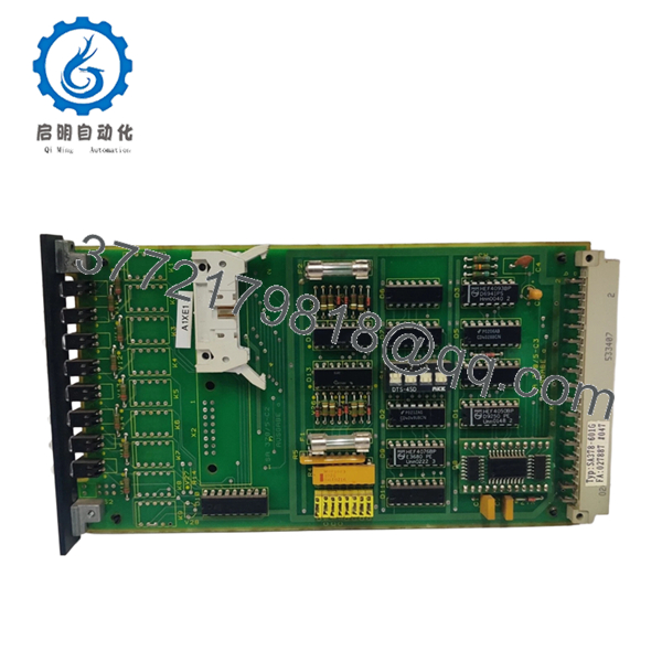
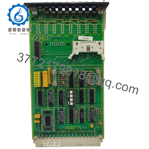
The Noris SA378-601G (incorporating the SA378-5-C3 design) is a sophisticated dual-channel speed sensor used in mission-critical marine applications. By integrating two independent sensing elements and a signal converter into a single housing, it provides a high-reliability solution for monitoring engine RPM, turbocharger speeds, or propeller shaft rotation. The 4–20 mA analog output allows for direct integration into Norimos 2000 or other DCS platforms without additional frequency-to-current transducers.
Strategically, the SA378 series represents a high-priority “Insurance Spare.” Because these sensors are mounted directly on vibrating, high-temperature engine components, they are subjected to significant environmental stress. Buying New Surplus ensures you are not receiving a “heat-fatigued” unit salvaged from a scrapped vessel. For fleet managers, maintaining an on-site inventory of these dual-channel units is essential to prevent “Single Point of Failure” incidents that can lead to emergency propulsion shutdowns or safety violations during inspection.

- SA378-601G
- SA378-601G
Installation & Configuration Guide
Stage 1: Pre-Installation (Prep & Safety)
- Safety First: Ensure the engine is locked out. Moving pole wheels can cause severe injury.
- Cleaning: Use a wire brush to clean the thread hole and the surface of the pole wheel (gear) to ensure accurate gap measurements.
- Redundancy Check: Identify which of the two channels is designated for the tachometer and which for the overspeed protection system.
Stage 2: Removal
- Unplug the sensor connector. Use a 24 mm wrench to loosen the lock nut.
- Unscrew the old SA378 unit. Inspect the tip for signs of physical contact with the gear; if damaged, check the gear for run-out issues.
Stage 3: Installation (Clone & Seat)
- Screw the new SA378-601G in until it gently touches the gear tooth.
- Back it out by approximately 1.0 mm to 1.5 mm (refer to your vessel’s technical file for the exact air gap).
- Tighten the lock nut firmly to 30–50 Nm.
Stage 4: Power-On & Testing
- Verify the 24 V DC loop power. Measure the stationary current (should be exactly 4 mA).
- Start the engine and verify that both channels provide consistent, jitter-free RPM readings on the bridge and ECR consoles.
Firmware/Software Versions & Upgrade Notes
- Frequency Scaling: The SA378-601G is factory-calibrated. The “-5” and “-601G” designations refer to the specific frequency range (Hz) mapped to the 4–20 mA output. Ensure this matches your existing sensor’s label.
- Analog Calibration: No software is required on the sensor itself, but the receiving PLC/I/O module must be scaled to the sensor’s specific RPM range (e.g., 4 mA = 0 RPM, 20 mA = 2500 RPM).
- Hardware Interoperability: This unit is a drop-in replacement for legacy SA378 variants, provided the thread size and output signal type are identical.
Frequently Asked Questions (FAQ)
What is the advantage of the dual-channel SA378-601G?
It provides two independent signals from a single mounting point. This is often required by classification societies for redundancy—one signal for the display and one for the safety system (Overspeed Trip).
Are these units refurbished?
No. We exclusively supply New Surplus or Original New parts. Refurbished speed sensors are notoriously unreliable because internal coil insulation breaks down over time due to engine heat, which can lead to intermittent signal loss.
Can I replace an SA378-5-C3 with an SA378-601G?
Yes, provided the technical specifications (scaling and thread) are verified against your system’s requirements. The “C3” usually refers to the connection style (e.g., cable length or plug type).
What happens if the air gap is too large?
If the gap between the sensor and the gear is too large, the signal will become intermittent or drop to 4 mA at low RPMs. If it’s too small, vibration may cause the sensor to strike the gear, destroying the unit.
How do I know if the sensor has failed?
A reading of 0 mA usually indicates a wiring break. A reading of 4 mA while the engine is spinning suggests the sensor is not “seeing” the gear teeth (gap too large or internal sensing failure). A reading of >20 mA suggests a short circuit or internal fault.


