
 WhatsApp: +86 16626708626
 Email:
  Phone: +86 16626708626
Description
3. Key Technical Specifications
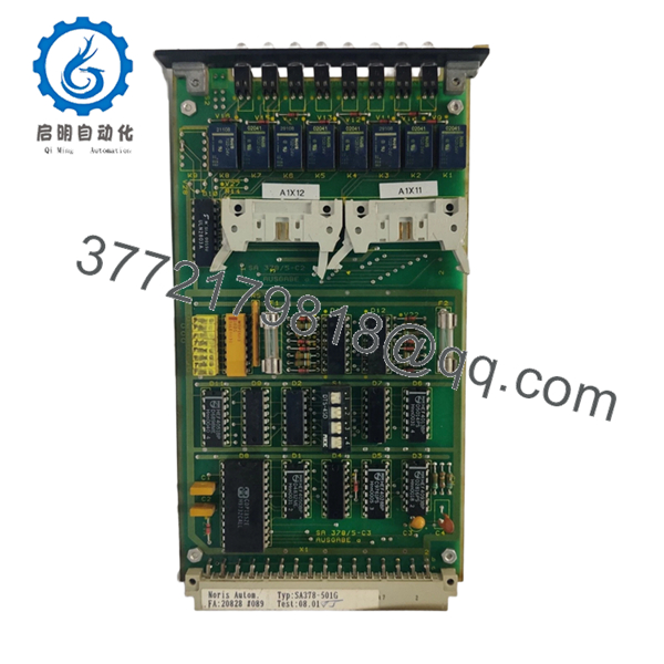
- Module Type: Binary I/O module (with relay outputs)
- System Compatibility: NORIMOS 2000 monitoring system
- Function: Digital input/output signal handling with relay switching
- Variants: SA378-501G, SA378-502G, SA378-511G
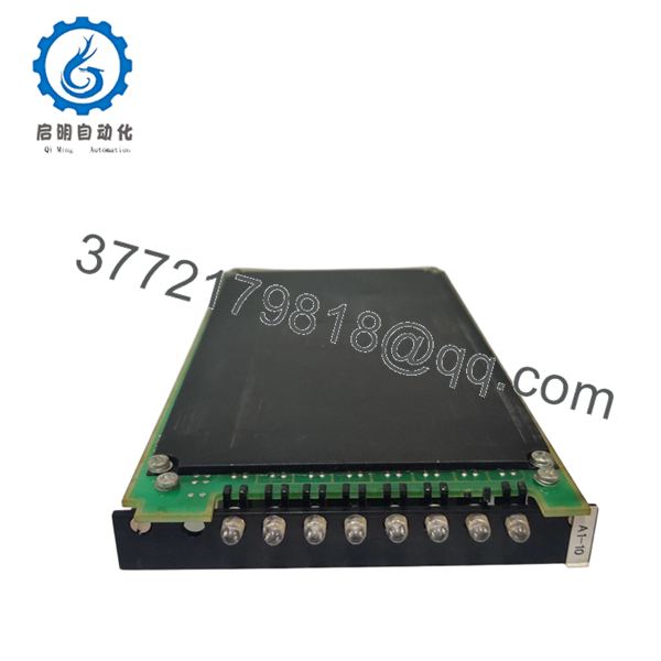
- Output Type: Relay-based outputs (galvanic isolation via contacts)
- Architecture: Plug-in PCB for 19″ rack system
- Communication: NORIS proprietary backplane bus
- Power Supply: Backplane-fed (typ. 24 V DC system)
- Application: Engine alarms, status signals, interlocks
- Mounting: Dedicated I/O slot in NORIMOS rack
- Certification Context: Part of Lloyd’s-approved NORIMOS system
4. Product Introduction
The NORIS SA378-501G is a relay-based digital I/O module used in NORIMOS 2000 marine monitoring systems. It handles binary signals—both inputs and outputs—typically for alarms, status indication, and safety interlocks.
In real installations, this module is used where hardwired relay outputs are required for engine shutdown logic or alarm annunciation. Compared to transistor-based variants (e.g., SA378-601G), the relay version is preferred when galvanic isolation and direct switching of field circuits are required.

- SA378-501G
- SA378-501G
5. Installation & Configuration Guide
Stage 1: Pre-Installation Preparation (10–15 min)
- ⚠️ Safety First:
- Inform engine control room
- Shut down monitoring system
- Isolate 24 V DC supply
- Lock out/tag out
- Wait 5 minutes
- Tools Required:
- ESD wrist strap
- PH1 screwdriver
- Multimeter (Fluke 115 or equivalent)
- Wire labels
- Smartphone
- Data Backup:
- Photograph all wiring terminals
- Document relay assignments (critical)
- Record alarm mapping
Stage 2: Removing the Old Module (5–10 min)
- Open cabinet and locate SA378 module
- Label all wiring (relay outputs are easy to mix up)
- Disconnect terminal blocks carefully
- Release rack locking tabs
- Pull module straight out
- ⚠️ Note:
Relay wiring errors here can cause false shutdown signals later
Stage 3: Installing the New Module (10 min)
- Wear ESD protection
- Confirm exact model (501G vs 601G matters)
- Insert module into correct slot
- Reconnect wiring exactly as documented
- Secure locking tabs
- Self-Checklist:
- Correct module type (relay vs non-relay)
- Wiring matches original
- Module fully seated
Stage 4: Power-On & Testing (15–20 min)
- Pre-Power Check:
- Verify no shorts on relay circuits
- Power-On Steps:
- Power rack only
- Observe system initialization
- Trigger test alarms
- Verify relay actuation (audible click + output confirmation)
- ⚠️ Troubleshooting Note:
- No relay action → check coil supply from backplane
- Continuous alarm → wiring mismatch or stuck relay
6. Frequently Asked Questions (FAQ)
Q1: What’s the difference between SA378-501G and SA378-601G?
The 501G uses mechanical relays. The 601G uses transistor outputs. If your system expects dry contacts, the 601G will not work.
Q2: Can I hot-swap this module?
No. This rack design predates hot-swap capability. Removing it live risks damaging the backplane or triggering false shutdowns.
Q3: Is this module obsolete?
Yes. Fully obsolete. Availability is limited to secondary markets and ship-breaking supply chains.
Q4: What happens if I install the wrong variant?
I’ve seen this firsthand—installing a 601G in place of a 501G resulted in alarms not triggering shutdown relays. The system looked “fine” until a real fault occurred. That’s a dangerous situation.
Q5: Are relay outputs still reliable on these old modules?
Depends on condition. Relay contacts wear over time. Always request load-tested units. Bench tests alone aren’t enough.
Q6: Why are these modules still expensive?
Because they’re critical and scarce. When a vessel is down, operators pay for immediate availability—not for newness.
Q7: Do I need to reconfigure anything after replacement?
No software configuration. But wiring defines behavior. Any mistake there becomes a logic fault.


