
 WhatsApp: +86 16626708626
 Email:
  Phone: +86 16626708626
Description
Key Technical Specifications
| Parameter | Value |
| Measuring Principle | Magnetic-inductive (contactless) |
| Output Signal | 4–20 mA (Proportional to frequency) |
| Supply Voltage | 18–32 V DC (Nominal 24 V DC) |
| Thread Size | M16 x 1.5 |
| Material | Stainless Steel (V4A) / Marine-grade Brass |
| Scanning Distance | 0.5 mm to 2.0 mm (Typical) |
| Protection Class | IP67 (Dust tight and water immersion resistant) |
| Connection | Integrated plug-in connection (G-type) |
| Operating Temp | -25 °C to +100 °C (Heavy-duty thermal range) |
Product Introduction & Supply Chain Strategy
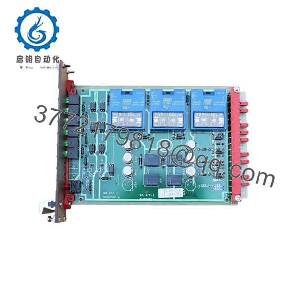
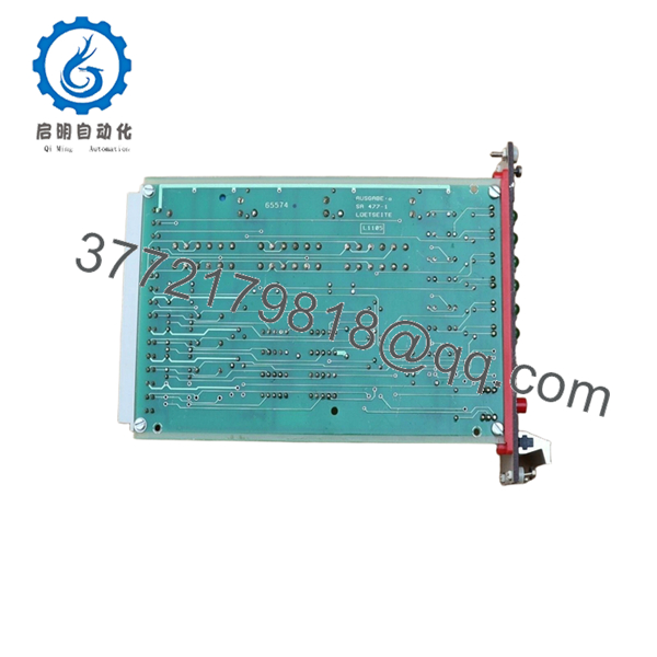
The Noris SA477-3G is a specialized magnetic-inductive speed sensor featuring an integrated frequency-to-current converter. Unlike basic passive pickups, the SA477-3G processes raw pulse data internally and transmits a stabilized 4–20 mA signal. This design is engineered to eliminate electromagnetic interference (EMI) issues, making it the standard for long-distance signal transmission in marine engine rooms and industrial turbine halls.
Maintaining a New Surplus SA477-3G in your inventory is a vital Supply Chain strategy for mitigating Total Cost of Ownership (TCO). Because these sensors are often mounted in high-vibration, high-heat zones near the flywheel or turbocharger, they are considered primary failure points. By sourcing “New Surplus” rather than refurbished junk, you ensure the internal signal-processing electronics have not been degraded by previous thermal cycling. This is an essential “insurance policy” part to keep on-site to prevent unplanned downtime or vessel detention.
Installation & Configuration Guide
Stage 1: Pre-Installation (Prep & Safety)
- Lock-out/Tag-out: Ensure the engine is fully stopped and the start-sequence is disabled.
- Cleaning: Clean the mounting port and the target pole wheel (gear teeth). Any metal filings on the sensor tip will distort the signal.
- Tool Check: You will need a 22 mm or 24 mm wrench (depending on the lock-nut) and a non-magnetic feeler gauge.
Stage 2: Removal
- Disconnect the cable plug. Loosen the lock-nut and unscrew the old sensor.
- Inspect the old sensor tip; if it shows physical grinding marks, the air gap was too tight or the shaft has excessive run-out.
Stage 3: Installation (Clone & Seat)
- Screw the SA477-3G in by hand until it gently touches the gear tooth.
- Back the sensor out by approximately 1.0 mm (standard air gap).
- Tighten the lock-nut firmly to ensure vibration does not cause the sensor to shift into the rotating gear.
Stage 4: Power-On & Testing
- Apply 24 V DC power. Verify the loop current is 4 mA while the gear is stationary.
- Once the engine starts, verify that the mA signal increases linearly with RPM. If the signal remains at 4 mA, the air gap is likely too large.

- SA477-3G
- SA477-3G
Firmware/Software Versions & Upgrade Notes
- Hardware Scaling: The SA477-3G is a hardware-configured device. The frequency range (e.g., 0–2000 Hz) is factory-set to correspond to the 4–20 mA output.
- Verification: Always verify that the pulse-per-revolution (number of teeth) on your flywheel matches the original system design to ensure the analog output remains accurate.
- Zero Software Hassle: This is a field-level analog device; it requires no firmware updates or software handshake, ensuring a true “plug-and-play” replacement for legacy Noris speed systems.
Frequently Asked Questions (FAQ)
Why should I choose New Surplus over a cheaper refurbished unit?
Speed sensors contain delicate copper windings and internal conversion circuitry. Refurbished units are often pulled from old engines where they have been “baked” for years. This leads to insulation breakdown that causes intermittent signal loss at high temperatures—a risk that far outweighs the cost savings.
What is the difference between an “SA” and a “VSA” sensor?
“SA” generally refers to the standard speed sensor line with integrated converters, while “VSA” may refer to variants with different amplification or voltage characteristics. The SA477-3G is specifically a 4–20 mA current-loop device.
Can this sensor be used for overspeed protection?
Yes, the SA477-3G is frequently used for both tachometer display and overspeed trip logic. Its 4–20 mA output is compatible with most marine safety modules and PLCs.
How do I troubleshoot a constant 20 mA signal?
A 20 mA or higher (saturated) signal usually indicates an internal short circuit or that the sensor is positioned too close to the gear, causing constant saturation. Re-check the air gap and the wiring for shorts.
What is the “3G” designation?
The “3G” typically specifies the electrical connection type (integrated plug) and the specific frequency scaling range. Always match this suffix exactly to ensure the replacement is compatible with your display scaling.


