
 WhatsApp: +86 16626708626
 Email:
  Phone: +86 16626708626
Description
Key Technical Specifications
| Parameter | Value |
|---|---|
| Manufacturer | OLEC |
| Part Number | 64VB412V02 |
| Product Type | HF1 Variable Blower Control Board |
| Board Function | Variable blower control |
| Nominal System Variant | 220 VAC |
| Frequency Variant | 60 Hz |
| Related Equipment | OLEC AP30-5000 / AP30-8000 |
| Related Blower Assembly | 62BLO02 |
| Related Exhaust Assembly | 62HF1-2-60 |
| Related Voltage Selector | 64VS409 |
| PCB Family | 64VB412 series |
| Related 50 Hz Variant | 64VB412V01 |
| Related 60 Hz 120 V Variant | 64VB412V00 |
| Application | HF1 exhaust/blower system |
| Lifecycle | Legacy / discontinued |
The historical parts documentation is particularly useful here because it distinguishes the 64VB412 variants by electrical configuration: 64VB412V00 = NC-120V-60Hz, 64VB412V01 = 220V-50Hz, and 64VB412V02 = NC-220V-60Hz.
The AP30 equipment parts list places 64VB412V02 immediately alongside the 62BLO02 HF1 blower assembly, 62HF1-2-60 exhaust system, and 64VS409 assembled voltage selector, establishing its role within the blower/exhaust subsystem.
Important identification note: Online secondary-market descriptions for this part are inconsistent. Some sellers classify it generically as a PLC/control-system spare, while the historical OLEC documentation gives the much more specific identification: HF1 variable blower control board, 220 V, 60 Hz. For engineering replacement, use the board marking and machine documentation rather than a generic reseller category.
Product Introduction
The OLEC 64VB412V02 is a dedicated HF1 variable blower control PCB used in OLEC AP30-5000/AP30-8000 equipment. Historical OLEC documentation specifies the V02 version for 220 VAC, 60 Hz operation and lists it as part of the HF1 exhaust/blower assembly.
This is an equipment-specific control board, not a general-purpose PLC output module. The V00, V01, and V02 variants have different voltage/frequency designations, so substituting another 64VB412 revision without checking the machine’s electrical configuration is not advisable.
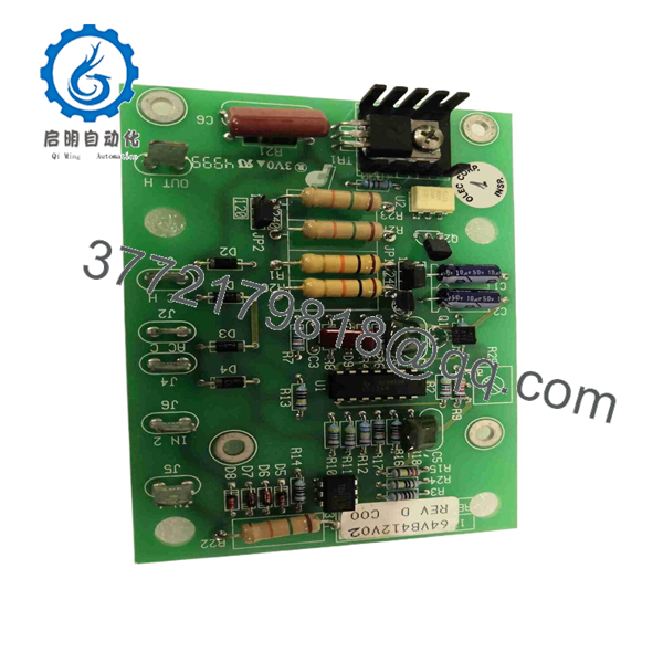
64VB412V02
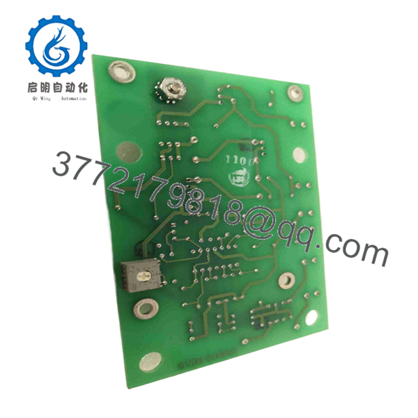
64VB412V02
Installation & Configuration Guide
Stage 1: Pre-Installation Preparation
Estimated time: 20–30 minutes
⚠️ Safety First: The V02 board is associated with a 220 VAC / 60 Hz HF1 blower circuit. Apply the equipment manufacturer’s LOTO procedure before opening the AP30 equipment cabinet.
Tools Required:
- ESD wrist strap
- CAT-rated digital multimeter
- Insulated screwdrivers
- Wire labels
- Smartphone/camera
- OLEC service documentation
Data Backup:
- Record the complete 64VB412V02 part number.
- Photograph the installed board from several angles.
- Photograph every wire and connector before removal.
- Record the position of adjustment components, if fitted.
- Identify the associated 62BLO02 blower assembly.
- Confirm the machine uses the 220 VAC / 60 Hz configuration.
- Record the position of the 64VS409 voltage-selector assembly where applicable.
- Photograph the surrounding HF1 wiring.
⚠️ Do not substitute the V01 or V00 board simply because the PCB family number matches. The historical parts list assigns different voltage/frequency configurations to these revisions.
Stage 2: Removing the Old Module
Estimated time: 15–20 minutes
- Place the equipment in its approved maintenance state.
- Apply LOTO to the applicable AC supply.
- Verify the 220 VAC supply is absent with a properly rated meter.
- Allow the equipment to discharge according to the OEM procedure.
- Photograph the board and wiring.
- Label each connector and conductor.
- Disconnect the blower-control wiring carefully.
- Remove the PCB mounting hardware.
- Lift the board without stressing attached wiring.
- Inspect the mating connectors and wiring for heat damage.
⚠️ Look for heat-discolored terminals or PCB areas. A failed blower-control board may be the result of a blower motor, wiring, or overload problem rather than the primary fault.
Stage 3: Installing the Replacement
Estimated time: 15–25 minutes
- Verify the replacement marking is 64VB412V02.
- Confirm the 220 VAC / 60 Hz configuration.
- Compare connector locations with the original board.
- Inspect the replacement PCB for damaged components or contamination.
- Install the board in the original mounting position.
- Secure all mounting hardware.
- Reconnect each connector according to the photographs and wiring documentation.
- Verify the blower-control wiring.
- Confirm the voltage-selector configuration where applicable.
- Check that no wires are trapped beneath the PCB.
Self-Checklist:
- 64VB412V02 verified
- 220 VAC confirmed
- 60 Hz confirmed
- Connector positions matched
- Blower wiring checked
- Voltage selector checked
- PCB mounting secure
- No loose conductors
Stage 4: Power-On & Testing
Estimated time: 30–45 minutes
- Perform a final visual inspection.
- Verify there are no exposed or shorted conductors.
- Check the applicable AC supply with a meter.
- Restore equipment power.
- Observe the HF1 blower-control circuit during startup.
- Verify the blower starts correctly.
- Check blower operation at the commanded speed range.
- Monitor for abnormal motor noise or vibration.
- Check the exhaust airflow.
- Verify that the equipment reports no blower-related alarms.
- Run the applicable machine maintenance/diagnostic sequence.
- Return the equipment to production only after the blower system has passed its operational checks.
⚠️ Do not assume a blower-control PCB is the only possible cause of a blower fault. Check the blower motor, supply voltage, wiring, voltage selector, and mechanical condition before condemning the replacement board.
Frequently Asked Questions (FAQ)
What is OLEC 64VB412V02?
The 64VB412V02 is an HF1 variable blower control board used in OLEC equipment. Historical parts documentation lists it directly as “HF1 Variable blower ctrl” and associates it with the 62BLO02 blower assembly.
What voltage and frequency does 64VB412V02 use?
The historical OLEC parts catalog identifies 64VB412V02 as the 220 V / 60 Hz HF1 control-board variant.
What equipment uses 64VB412V02?
The available parts documentation places the board in OLEC -5000 and -8000 equipment. It is listed alongside the HF1 blower and exhaust-system components.
Is 64VB412V02 interchangeable with 64VB412V01?
Not without verification. The historical parts catalog identifies V01 as the 220 V / 50 Hz version and V02 as the 220 V / 60 Hz version. Frequency differences are enough to make an unverified substitution inappropriate.
What is the difference between V00, V01, and V02?
The historical catalog identifies the variants as:
- 64VB412V00: 120 V / 60 Hz HF1 control board
- 64VB412V01: 220 V / 50 Hz HF1 control board
- 64VB412V02: 220 V / 60 Hz HF1 control board
These designations should be treated as electrical configuration identifiers, not cosmetic revision numbers.
Is 64VB412V02 a PLC module?
No. The available OLEC documentation identifies it as a dedicated HF1 variable blower control board, not a conventional PLC CPU, I/O module, or communications card.
Is 64VB412V02 obsolete?
It is a legacy OLEC equipment component. Current market listings are primarily secondary-market industrial spare-parts listings rather than current OEM production documentation.
What should procurement verify before ordering?
Request photographs of the actual board showing:
- 64VB412V02 marking
- PCB revision/serial information
- Connector arrangement
- Component condition
- Any adjustment potentiometers or switches
- Associated machine model
- Functional-test status
- Condition: New Original / New Surplus / Refurbished
For this part, the V02 suffix is critical. The historical OLEC parts catalog explicitly differentiates V00, V01, and V02 by supply voltage and frequency.



