
 WhatsApp: +86 16626708626
 Email:
 Phone: +86 16626708626
Description
Core Product Summary
The Omron R88A-NCW152-DRT is a DeviceNet Option Unit for the OMNUC W series of AC servo drivers (R88D-WT models with R88M-W servomotors). Mounted to the side of the servo driver, it turns the driver into a slave node on a DeviceNet field network, so motion commands, parameter data, and status information can be exchanged with a host controller over the network instead of through hardwired pulse or analog command lines.
The unit supports both Remote I/O communications and Explicit Message communications, and it includes built-in positioning capability: move commands such as JOG, Step, and Station commands, origin search, point table operation, multi-speed positioning, and notch signal output positioning can be executed without a separate positioner. Rotary switches set the node address and baud rate, and the network connector is a Phoenix Contact MSTB 2.5/5-STF-5.08AUM screw terminal block. The board attaches to OMNUC W-series drivers with software version 14 or later, is configurable for use as a linear or rotary axis, supports Omron servomotors with absolute encoders, and can be set up and monitored from a personal computer using the Setup Tool connected through the unit’s CN11 connector.
Key Technical Specifications
| Parameter | Value |
|---|---|
| Product type | DeviceNet option board (fieldbus interface) for servo drivers |
| Applicable drives | OMNUC W-series AC Servo Drivers (R88D-WT), software version 14 or later |
| Network | DeviceNet open field network; unit operates as a slave |
| Communications types | Remote I/O communications and Explicit Message communications |
| Node address | Set with rotary switch |
| Baud rate | Set with rotary switch |
| DeviceNet communications connector | Phoenix Contact MSTB 2.5/5-STF-5.08AUM (5-pin screw terminal) |
| Additional connectors | CN4 (I/O signal connections for the DeviceNet Unit, including fully-closed encoder connection), CN11 (Setup Tool connection) |
| Positioning functions | JOG, Step, and Station move commands; origin search; point table; multi-speed positioning; notch signal output positioning |
| Axis configuration | Selectable as linear axis or rotary axis |
| Encoder support | Supports OMRON servomotors with absolute encoders (R88M-WT/-WS types) as well as incremental encoders; fully-closed control connection supported |
| Monitoring functions | Remote I/O readback of Servo Driver monitor-mode status; data tracing with configurable sampling cycle via Explicit Messages |
| Setup Tool connection | Personal computer via special cable R88A-CCW002P4 connected to CN11; software supplied as Setup Tool Software (SBCE-001) |
| Network configuration tool | OMRON DeviceNet Configurator, version 2.2 or later (connected via RS-232C etc.) |
| Device definition | EDS files support multivendor slave integration |
| Supplied accessories | Communications connector (Phoenix Contact MSTB 2.5/5-STF-5.08AUM), 3 ground screws (pan head M3 x 10, M4 x 8, and M4 x 10; the screws used depend on the Servo Driver model) |
Detailed Product Overview
In a conventional OMNUC W servo system, the driver receives position commands as a pulse train or speed/torque commands as an analog voltage from a separate positioner or motion controller, with each axis wired individually back to the controller. The R88A-NCW152-DRT changes that architecture. Once the board is mounted to the side of the driver, the driver becomes a slave on a DeviceNet network, and a DeviceNet master — such as an OMRON DeviceNet Master Unit for CS/CJ-series programmable controllers — can command the axis over the same trunk cable that serves the network’s other slaves. This supports distributed servo configurations in which a single network manages multiple axes alongside I/O and other device types.
What sets this option unit apart from a simple communications adapter is that it includes positioning intelligence. Move commands issued over DeviceNet include a JOG command (moving the axis in a specified direction at a specified speed), a Step command (moving the axis a specified amount in a specified direction), and a Station command for rotary-axis applications. The unit also provides origin search parameters, a point table, multi-speed positioning, and notch signal output positioning, so positioning operations can be performed without a separate positioner or host motion controller. Positioning data, machine system and peripheral device parameters, speed/acceleration/deceleration parameters, and unit parameters are all set through the option unit’s parameter set.
Two communications mechanisms are available, and engineers will typically use both. Remote I/O communications handle cyclic command and status exchanges — the servo ON command, origin search command, direct operation command, and general command bits and status — while Explicit Message communications handle on-demand operations such as reading and writing parameters, setting trace parameters, and reading trace data. The tracing function collects operating data and I/O information at a specified sampling cycle and is started and read from a PLC or personal computer using Explicit Messages, which supports failure prediction and troubleshooting of the servo system. Parameters can also be changed over the network, with the manual directing users to confirm safety at the destination node before transferring parameters or changing output signals.
Integration requires attention to three dependencies. First, the firmware condition: the board attaches to OMNUC W-series servo drivers with software version 14 or later, so the driver version must be checked before planning an upgrade of an existing machine. Second, servo driver configuration: when the DeviceNet Unit is mounted, certain Servo Driver parameters are set automatically, and standard settings for I/O signals, analog monitors, stop modes, and rotation direction are applied as described in the manual. Third, network design: communications power must be provided to the network, and the manual defines DeviceNet network configuration restrictions and noise countermeasures for the communications line. The unit’s LED indicators and alarm/warning code tables support on-site diagnosis, and the Setup Tool software allows parameter setting, changing, and monitoring from a personal computer connected to the front CN11 connector.
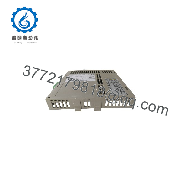
R88A-NCW152-DRT
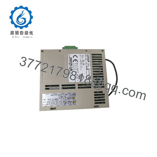
R88A-NCW152-DRT
System Compatibility & Integration Requirements
| Item / Dependency | Verified Compatibility or Requirement | Practical Note |
|---|---|---|
| Applicable servo drivers | OMNUC W-series AC Servo Drivers (R88D-WT), software (firmware) version 14 or later | All drivers from this firmware version onward accept the board; verify driver version before ordering or installing |
| Applicable servomotors | OMNUC W-series AC Servomotors (R88M-W); incremental (R88M-WH/-WL) and absolute (R88M-WT/-WS) encoder types | With an absolute encoder, no origin search is required after startup once the origin has been set |
| Network role | DeviceNet slave; DeviceNet is an open field network governed by ODVA | Multivendor networks supported using EDS files defining device ID, parameters, and operating information |
| Host master | DeviceNet Master Unit for OMRON CS/CJ-series programmable controllers | Ladder-programming examples (servo ON, origin search, direct operation, parameter read) are given in the unit manual |
| Network configuration | OMRON DeviceNet Configurator version 2.2 or later | Connected via RS-232C or similar; used to set and change parameters easily over DeviceNet |
| Communications types | Remote I/O communications and Explicit Message communications | Remote I/O for cyclic control/status; Explicit Messages for parameter transfer, tracing, and set/read commands |
| Node address / baud rate | Set using rotary switches on the unit | Confirm settings against the network configuration before powering the node |
| Setup Tool | Personal computer software; connection via cable R88A-CCW002P4 to CN11 connector on the front of the unit | Setup Tool Software model SBCE-001 |
| Axis mode | Configurable as a linear axis or a rotary axis | Station command applies when used as a rotary axis |
| Network power | Communications power supply must be provided to the DeviceNet communications line | Follow the manual’s precautions for communications line design and noise countermeasures |
| PLC online edits | When used in a Programmable Controller system, execute online edits only after confirming that extending the cycle time causes no adverse effects | Otherwise input signals may not be readable |
Dimensions, Mounting & Connection Notes
| Item | Verified Value |
|---|---|
| Mounting location | Side of the OMNUC W-series Servo Driver |
| DeviceNet communications connector | Phoenix Contact MSTB 2.5/5-STF-5.08AUM (screw terminal type; one connector supplied with the unit) |
| I/O signal connector for the DeviceNet Unit | CN4 (connection example, terminal layout, and interface circuits given in the unit manual; supports fully-closed encoder connection) |
| Setup connector | CN11 on the front of the unit, for the R88A-CCW002P4 computer cable |
| Grounding | Ground screws (pan head M3 x 10, M4 x 8, M4 x 10) supplied; the screws used depend on the Servo Driver model; Servo Driver and Servomotor frame ground terminals must be connected to a class-3 ground (100 Ω or less) |
| Ground screws supplied | 3 |
Installation notes: mounting, wiring, and inspection must be performed with the power supply turned OFF and only after waiting at least five minutes for discharge, since terminals remain live even after power-off. The unit must be installed correctly and securely with mounting screws tightened to the torque specified in the relevant manuals; incorrect mounting can result in motor runaway. Wiring must use crimp terminals, not bare stranded wires. The unit shares the Servo Driver’s environment requirements: avoid direct sunlight, condensation, corrosive or flammable gases, iron dust, salts, shock and vibration, and exposure to water, oil, or chemicals, and observe the clearances specified between the Servo Driver and the control panel or other devices. Before touching the unit, discharge static buildup by touching a grounded metallic object.
FAQ
What is the Omron R88A-NCW152-DRT?
It is a DeviceNet Option Unit that mounts to the side of an OMNUC W-series AC servo driver (R88D-WT) and makes the driver function as a slave on a DeviceNet network, with built-in positioning functions so axes can be commanded over the network without a separate positioner.
Which servo drivers does it fit?
It attaches to OMNUC W-series AC Servo Drivers with software version 14 or later; the driver firmware version is the key compatibility condition to check.
What can be commanded over the network?
Remote I/O communications carry cyclic commands and status (servo ON, origin search, direct operation, and general command bits and status), while move commands include JOG, Step, and Station commands, plus point table operation, multi-speed positioning, and notch signal output positioning.
How are parameters set and monitored?
Parameters can be set through the DeviceNet using an OMRON DeviceNet Configurator (version 2.2 or later) or the Setup Tool software (SBCE-001) running on a personal computer connected to the unit’s CN11 connector with the R88A-CCW002P4 cable; parameters can also be changed via Explicit Messages from a PLC.
How are the node address and baud rate configured?
Both are set with rotary switches on the unit, and LED indicators show the unit’s communication status.
Does it support absolute encoders?
Yes, OMRON servomotors with absolute encoders (R88M-WT/-WS types) are supported; once the origin is set after startup, no further origin searches are required. Incremental-encoder motors are also supported, and a fully-closed encoder connection is available through CN4.
Can the unit be used for maintenance diagnostics?
Yes, the tracing function collects operating data and I/O information at a specified sampling cycle, started and read via Explicit Messages from a PLC or personal computer, to help predict or troubleshoot servo system failures. Monitor-mode status of the Servo Driver can also be read to a PLC through Remote I/O communications.
What wiring accessories are supplied?
The unit ships with one DeviceNet communications connector (Phoenix Contact MSTB 2.5/5-STF-5.08AUM) and three pan-head ground screws (M3 x 10, M4 x 8, and M4 x 10); the ground screws used depend on the Servo Driver model.
4



