
 WhatsApp: +86 16626708626
 Email:
  Phone: +86 16626708626
Description
Key Technical Specifications
| Parameter | Specification |
|---|---|
| Manufacturer | Pacific Scientific |
| Product Series | 6410 |
| Model | 6410-001-C-N-N |
| Product Type | Stepper / microstepping drive |
| DC Input Voltage | 24–75 VDC |
| Rated Phase Current | 5 A RMS |
| Peak Phase Current | 7.1 A peak |
| Chopper Frequency | 20 kHz |
| Maximum Step Rate | 2 MHz, filter out |
| Heat Sink | None |
| Cover | Included |
| Connector Kit | Not included |
| Dimensions | 5.00 × 1.50 × 4.30 in |
| Operating Temperature | 0 to 50 °C |
| Storage Temperature | −55 to 70 °C |
| Approx. Weight | 0.97 lb / 0.44 kg |
The 6410-001-C-N-N is documented as a 6410-series microstepping drive with a 24–75 VDC supply range, 5 A RMS rated phase current, 7.1 A peak current capability, and a 20 kHz chopper frequency. The ordering code indicates a standard cover, no heat sink, and no connector kit.
Product Introduction
The Pacific Scientific 6410-001-C-N-N is a 6410-series microstepping drive for controlling two-phase hybrid stepper motors. It accepts a 24–75 VDC supply and regulates motor phase current up to 5 A RMS, with 7.1 A peak capability in microstepping operation. It is intended for industrial motion applications requiring controlled incremental positioning.
This specific configuration includes the standard cover but does not include a heat sink or connector kit. That configuration detail matters when replacing an installed 6410 drive because nearby variants such as 6410-001-C-N-K use a different connector-kit option. The 6410-001-C-N-N is also listed as discontinued, making exact part-number verification important for legacy equipment maintenance.
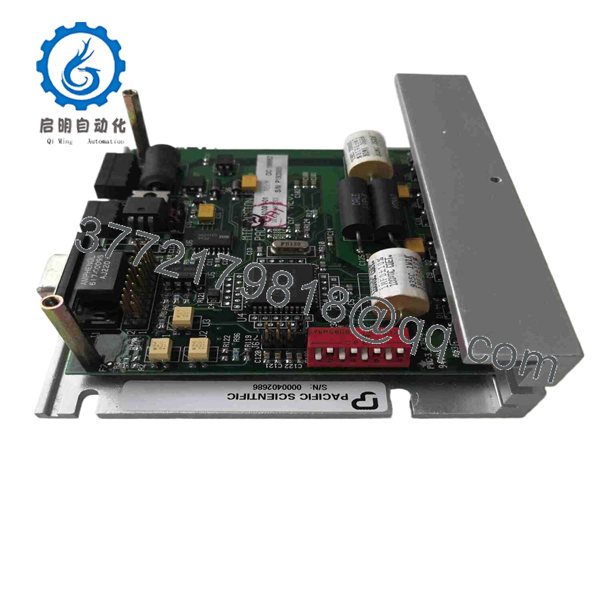
6410-001-C-N-N
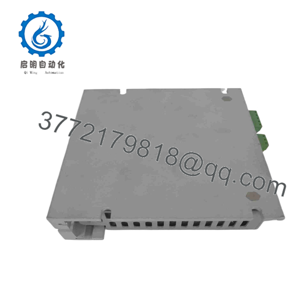
6410-001-C-N-N
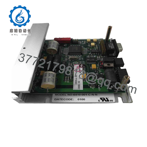
6410-001-C-N-N
Installation & Configuration Guide
Stage 1 — Pre-Installation Preparation
Estimated time: 20–30 minutes
- Notify machine operations and place the motion system in a controlled maintenance state.
- Stop commanded motion and apply the machine’s approved LOTO procedure.
- Isolate the 24–75 VDC drive supply.
- Wait at least 5 minutes before accessing the drive and verify that hazardous voltage has discharged.
- Wear an ESD wrist strap when handling the drive electronics.
- Prepare:
- PH1 screwdriver
- Digital multimeter
- Wire labels
- Camera/phone
- Approved wiring diagram
- Existing drive parameter/DIP-switch documentation
- Photograph the existing drive and every connector before removal.
- Record the existing model and configuration code.
⚠️ Verify the complete ordering code: 6410-001-C-N-N. The final N indicates that the connector kit is not included; do not assume a nearby 6410 variant is mechanically or electrically identical.
Stage 2 — Removing the Old Module
Estimated time: 15–25 minutes
- Confirm that the DC bus and control supply are isolated.
- Label motor, power, and command wiring.
- Photograph terminal positions and any DIP-switch settings.
- Disconnect wiring using the approved service procedure.
- Remove the drive’s mounting hardware.
- Withdraw the drive without stressing terminal blocks or signal wiring.
- Inspect the mounting panel and wiring for:
- Loose terminals
- Damaged insulation
- Heat discoloration
- Contamination
- Grounding problems
- Keep the original unit available until the replacement passes testing.
⚠️ A failed stepper drive is not necessarily the root cause. Check the motor windings, DC supply, controller pulse signals, and grounding before declaring the old drive defective.
Stage 3 — Installing the New Module
Estimated time: 20–30 minutes
- Compare the replacement with the original unit.
- Confirm 6410-001-C-N-N on the product label.
- Verify that the replacement has the expected cover configuration.
- Confirm that the installation does not depend on a heat sink that this model does not provide.
- Verify the motor’s rated current against the drive’s selected current setting.
- Reproduce approved DIP-switch settings from the original installation documentation.
- Mount the drive securely on the control panel.
- Reconnect DC input, motor phases, command signals, and ground according to the approved schematic.
- Perform a continuity and polarity check before applying power.
⚠️ Do not set the output current by simply copying a switch position from memory. Verify the motor’s rated phase current and the applicable 6410 configuration table. Incorrect current selection can cause motor overheating or insufficient torque.
Stage 4 — Power-On & Testing
Estimated time: 30–60 minutes
- With power isolated, check for unintended shorts across the DC input.
- Verify DC supply polarity and measured voltage.
- Energize the drive with the motor safely coupled or mechanically secured.
- Check for abnormal drive indications or immediate overcurrent behavior.
- Apply a low-frequency step command.
- Verify:
- Correct rotation direction
- Stable starting
- No excessive audible resonance
- No missed steps at low speed
- Correct motor current
- Gradually increase command frequency while monitoring motor temperature.
- Test acceleration and deceleration under the actual machine load.
- Confirm the controller’s commanded position agrees with the mechanical position.
- Record final DIP settings, supply voltage, motor current, and test results.
⚠️ Do not assume that a motor will run correctly simply because the drive powers up. A stepper system can energize normally while still having incorrect phase wiring, current selection, command polarity, or mechanical loading.
For a legacy 6410 replacement, a useful QC record should include incoming visual inspection, model/revision traceability, supply-voltage verification, motor-phase checks, configuration verification, controlled motion testing, and final packaging/ESD protection.
Frequently Asked Questions (FAQ)
1. What is the Pacific Scientific 6410-001-C-N-N?
It is a 6410-series microstepping stepper drive designed to regulate current to two-phase hybrid stepper motors. It operates from 24–75 VDC and is rated for 5 A RMS phase current with 7.1 A peak capability.
2. What does the C-N-N configuration mean?
The C identifies the standard cover option. The first N indicates no heat sink, while the second N indicates no connector kit.
3. Is the 6410-001-C-N-N discontinued?
Yes. Current distributor information identifies the model as discontinued by the manufacturer. Replacement units are therefore commonly sourced through surplus, refurbished, or industrial-spares channels.
4. What is the input voltage range?
The specified DC input range is 24–75 VDC. The 75 VDC maximum should not be exceeded.
5. What motor current can the drive provide?
The drive is rated for 5 A RMS phase current, with a reported 7.1 A peak capability in microstepping operation. The actual current setting must be selected according to the motor and applicable 6410 configuration documentation.
6. Does this model include a heat sink or connector kit?
No. The 6410-001-C-N-N configuration has no heat sink and no connector kit. Confirm this before ordering if the existing installation requires additional thermal hardware or connectors.
7. Can I replace it with another 6410-series drive?
Not without checking the complete part number. The 6410 family contains variants with different heat-sink, cover, connector-kit, and other configuration options. Match the existing 6410-001-C-N-N code, motor requirements, wiring, and controller interface before substitution.



