
 WhatsApp: +86 16626708626
 Email:
  Phone: +86 16626708626
Description
Key Technical Specifications
- Model: Pacific Scientific 6410-007-N-N-N
- Series: 6410 Stepper Drives
- Drive Type: Two-phase bipolar chopper stepper drive
- Motor Type: Two-phase bipolar stepper motor
- Primary Control Inputs: Step and direction
- DC Supply Range: 24–75 VDC
- Maximum RMS Phase Current: 5 A RMS
- Peak Current Rating: 7.1 A peak
- Recommended Maximum Current at 25 °C Ambient: 5 A RMS
- Recommended Maximum Current at 45 °C Ambient: 2.5 A RMS
- Thermal Installation: Bookcase mounting to a cooling plate or heat sink
- Maximum Recommended Chassis Temperature: Below 60 °C
- Natural-Convection Clearance: Approximately 4 in. above and below unit
- Product Status: Discontinued / legacy motion-control component
- Listed Weight: Approximately 0.86 lb
The available product data identifies the 6410-007-N-N-N as a 24–75 VDC, 5 A RMS, 7.1 A peak Pacific Scientific 6410 Series stepper drive for two-phase motors. Before installation, confirm the exact motor current, inductance, wiring type, control-input electrical standard, and the original drive’s suffix configuration against the machine documentation.
Product Introduction
The Pacific Scientific 6410-007-N-N-N is a 6410 Series bipolar chopper stepper drive used to convert step-and-direction commands into controlled winding current for a two-phase stepper motor. It is commonly found in legacy packaging equipment, indexing tables, assembly machinery, positioners, and OEM motion-control panels.
This model accepts a 24–75 VDC supply and provides up to 5 A RMS, or 7.1 A peak, motor current. Its output capability makes cooling and current setup critical: a drive that works at 5 A RMS near 25 °C ambient must be derated to 2.5 A RMS at up to 45 °C ambient.
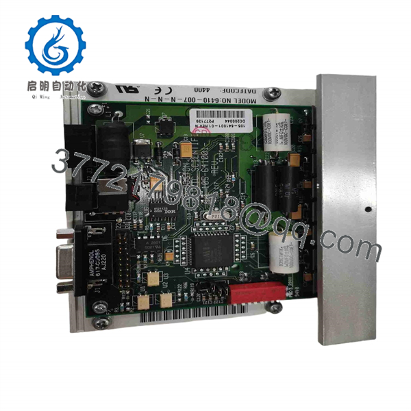
6410-007-N-N-N
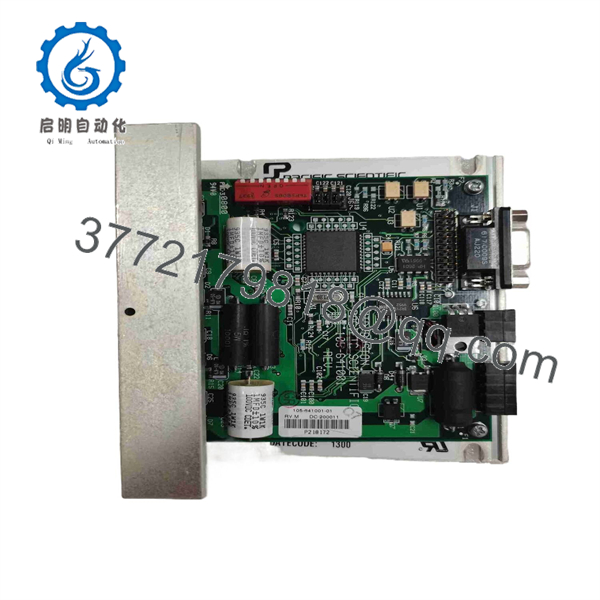
6410-007-N-N-N
Troubleshooting Quick Reference
| Symptom | Possible Cause | Relevance to this Part | Quick Check Method | Recommendation |
|---|---|---|---|---|
| No power or status indication | Missing DC bus voltage, blown fuse, reversed polarity, failed power supply | ❌ Low | Measure DC supply voltage at the drive power input. Verify a stable value within the required 24–75 VDC range with the machine enabled. | Check the upstream fuse, DC supply, disconnect, and terminal tightness before replacing the drive. |
| Motor does not move but holds position | Missing step pulses, inhibited drive, incorrect control wiring, mechanical jam | ⚠️ Medium | Check for holding torque with the drive enabled. Use an oscilloscope or high-speed meter to verify step pulses and direction changes at the command input. | If the motor holds but does not index, start with PLC, motion controller, encoder interface, and step/direction wiring. |
| Motor does not move and has no holding torque | Drive disabled, open motor winding, faulty output stage, missing DC supply | ✅ High | With power removed, measure motor winding resistance phase-to-phase and compare both phases. Restore power and verify the enable circuit and DC bus voltage. | Confirm motor and cabling first. Replace the drive if supply, enable, command wiring, and motor windings test correctly but no output current is present. |
| Motor vibrates but does not rotate | Incorrect motor phase wiring, excessive load, acceleration too high, resonance | ⚠️ Medium | Disconnect power, identify motor winding pairs with an ohmmeter, and verify phase wiring against the machine schematic. Reduce commanded speed and acceleration for a test. | Do not wire from memory. A swapped winding lead can produce vibration, heating, and zero usable torque. |
| Motor runs in the wrong direction | Direction input polarity wrong, controller logic reversed, motor leads swapped | ❌ Low | Command a short jog in a safe direction and measure the direction input state. Compare wiring to the original installation drawing. | Reverse the direction command in the controller or correct the motor lead arrangement only per the approved wiring diagram. |
| Drive overheats or trips after running | Current setting too high, poor heat sinking, blocked ventilation, high ambient temperature | ✅ High | Measure or verify commanded phase-current setting. Inspect the cooling plate and check chassis temperature with an infrared thermometer after 15–30 minutes under load. | Mount the drive vertically in bookcase orientation, keep about 4 in. of clearance above and below, and keep chassis temperature below 60 °C. Derate current at higher ambient temperatures. |
| Drive fails after a motor cable replacement | Shorted motor cable, phase-to-phase fault, phase-to-ground fault, wrong cable termination | ✅ High | With all power isolated, test each motor conductor to ground and conductor-to-conductor. Check for pinched cable insulation at machine axes and cable carriers. | Do not reconnect a suspect motor cable to a replacement drive. A shorted output cable can damage the output stage immediately. |
| Position errors or missed steps | Torque margin too low, mechanical binding, high acceleration, resonance, excess current demand | ⚠️ Medium | Mark the shaft or load, run a slow-speed test, then compare commanded and actual index count. Check couplings, belts, bearings, and load movement by hand with power off. | Treat missed steps as a motion-system issue until proven otherwise. Increasing current without checking heating and mechanics is how drives get cooked. |
| Motor current is unstable or machine stalls at mid-speed | Stepper resonance, motor back-EMF, unsuitable acceleration profile, supply voltage drop | ⚠️ Medium | Record the speed range where the stall occurs. Monitor DC bus voltage while the motor accelerates and test at reduced acceleration. | Adjust acceleration and speed profile first. Confirm power supply capacity and motor-drive matching before replacing the unit. |
| Multiple axes stopped simultaneously | Common control supply loss, E-stop chain open, PLC output failure, shared enable signal fault | ❌ Low | Check whether other drives lost enable at the same time. Measure the shared DC bus and trace the safety or machine-enable circuit. | A common-mode failure almost never points to one individual 6410 drive. Check the panel supply and control logic before ordering hardware. |
❗ Current-setting warning: Do not assume that a replacement 6410-007-N-N-N can run at the old machine setting without checking ambient temperature and cooling. At 25 °C ambient, the drive can run at 5 A RMS; at up to 45 °C ambient, the referenced guidance limits it to 2.5 A RMS. That is not a small detail. It can decide whether the drive survives the first production shift.
❗ Motor wiring warning: Take photos of every motor lead, command terminal, shield termination, and power terminal before removing the old drive. A two-phase stepper can buzz, overheat, or lose torque if the winding pairs are crossed. Don’t wire from memory. Even experienced technicians get caught by a motor cable that was reworked years ago.
❗ ESD and power warning: Isolate the DC bus and wait for stored energy to discharge before touching motor terminals. Use a grounded wrist strap when handling the replacement drive. I have seen a replacement motion card fail before startup because someone handled it in dry weather and then connected a questionable motor cable.
Keep these checks in mind and you will save yourself most of the typical rework time. If the fault remains unclear, provide technical support with clear photos of the drive label, terminal wiring, DC supply measurement, motor winding readings, and controller fault history.
Frequently Asked Questions (FAQ)
Q: What is the Pacific Scientific 6410-007-N-N-N?
A: It is a Pacific Scientific 6410 Series two-phase bipolar chopper stepper drive. The drive receives step and direction commands from a motion controller or PLC interface, then regulates current through a two-phase stepper motor to create controlled position and speed movement. It is a drive, not a motor.
Q: What supply voltage does the 6410-007-N-N-N require?
A: The available specification identifies a 24–75 VDC input range. Verify the voltage at the drive terminals under actual axis motion, not only with the axis idle. A weak supply can look acceptable with no load, then collapse during acceleration and create nuisance stalls or drive faults.
Q: How much motor current can this drive provide?
A: The 6410-007-N-N-N is rated at 5 A RMS and 7.1 A peak. That rating depends on cooling and ambient temperature. The referenced installation guidance allows 5 A RMS at up to 25 °C ambient but calls for a 2.5 A RMS limit at ambient temperatures up to 45 °C. Check the motor nameplate and original current setting before applying power.
Q: Can I replace a 6410-007-N-N-N with a different 6410 Series drive?
A: Not automatically. The 6410 family can include different current ratings, option codes, interface arrangements, and factory-assigned customization identifiers. A physically similar drive may have a different current range or input configuration. Match the complete part number, not merely “6410,” and compare the installed wiring diagram, motor current setting, supply voltage, and command-interface requirements.
Q: Is the 6410-007-N-N-N hot-swappable?
A: No. Shut down and isolate the DC supply before removal. This is a standalone motion drive, not a hot-swappable PLC I/O module. Pulling or reconnecting motor wiring under power can damage the output stage, arc terminals, or create an uncontrolled axis movement when power returns.
Q: Will the machine program be lost if I replace this drive?
A: Usually, the PLC or motion-controller program remains intact because it resides in the controller, not in the stepper drive. However, the drive’s current adjustment, switch settings, jumpers, and terminal wiring may be local to the panel. Photograph and document those details before replacement. The software may survive, but an incorrect current or command-input setting can still prevent the axis from running.
Q: Is this model obsolete, and should I keep a spare?
A: It is identified by aftermarket sources as discontinued or legacy equipment. If the machine is still production-critical, a verified spare can be sensible because a modern replacement may require rewiring, control-signal conversion, motor retuning, safety review, and machine recommissioning. Confirm inventory and test status before scheduling an outage.
Q: Why is a New Surplus 6410-007-N-N-N less expensive than factory-sourced hardware?
A: New Surplus generally means unused original inventory from excess stock, project cancellations, liquidation, or stored maintenance spares. It may be supplied without current factory channel support, and packaging or accessories may differ. Before purchase, request photos of the exact label and terminals, condition classification, incoming inspection results, power-up verification, motor-output test procedure, warranty period, and shipping lead time.



