
 WhatsApp: +86 16626708626
 Email:
  Phone: +86 16626708626
Description
Key Technical Specifications
| Parameter | Specification |
|---|---|
| Manufacturer | Pacific Scientific |
| Series | 6410 |
| Model | 6410-009-N-N-N |
| Product Type | Microstepping Stepper Drive |
| DC Input | 24–75 VDC |
| Maximum Phase Current | 5.0 A RMS |
| Peak Phase Current | 7.1 A peak |
| Chopper Frequency | 20 kHz |
| Maximum Step Frequency | 2.0 MHz, filter off |
| Minimum Step Pulse | 250 ns, filter off |
| Maximum Resolution | 51,200 steps/revolution |
| Bus Overvoltage Trip | 83 VDC |
| Idle Current Reduction | 50% |
| Maximum Chassis Temperature | 60 °C |
| Ambient Operating Temperature | Up to 50 °C |
| Dimensions | 5.0 × 1.5 × 4.3 in |
| Motor Connector | 5-contact plug-in screw terminal |
| Power Connector | 3-contact plug-in screw terminal |
| Signal Connector | 9-socket D-sub miniature |
| Heat Sink | Not included |
The 6410-009-N-N-N is documented as a Pacific Scientific 6410-series microstepping drive with 24–75 VDC input, 5.0 A RMS maximum phase current, 7.1 A peak current, and a 20 kHz bipolar chopper. Its command interface supports up to 2.0 MHz step frequency with the digital filter disabled, while resolution can reach 51,200 steps/revolution for a 1.8° stepper motor.
The N-N-N configuration is important when replacing an installed unit. Available product records identify this model as a configuration without a heat sink, while connector details include separate motor, power, and signal interfaces. Do not substitute another 6410 variant without checking the complete ordering code and cabinet thermal arrangement.
Product Introduction
The Pacific Scientific 6410-009-N-N-N is a digital microstepping drive for two-phase stepper motors used in industrial positioning, indexing, inspection, dispensing, and other motion-control equipment. It accepts 24–75 VDC and regulates motor phase current up to 5.0 A RMS, with a reported 7.1 A peak current capability.
This version is particularly relevant to legacy machine maintenance because the complete configuration code determines the supplied hardware. The unit has no heat sink, supports up to 2.0 MHz step commands with filtering disabled, and provides up to 51,200 steps/revolution. Exact motor-current settings, wiring, and command configuration must be checked against the machine documentation before replacement.
Installation & Configuration Guide
Stage 1 — Pre-Installation Preparation
Estimated time: 20–30 minutes
- Notify machine operations and place the axis in an approved maintenance state.
- Stop all commanded motion and apply the machine’s LOTO procedure.
- Isolate the 24–75 VDC drive supply.
- Wait at least 5 minutes before accessing the drive.
- Verify the supply has discharged using an appropriately rated multimeter.
- Wear an ESD wrist strap when handling the electronics.
- Prepare:
- PH1 screwdriver
- Digital multimeter
- Wire labels
- Camera/phone
- Approved machine schematic
- Existing 6410 configuration documentation
- Photograph all connectors and DIP-switch positions before removal.
- Record the exact label information on the old drive.
⚠️ Critical: Confirm the entire part number is 6410-009-N-N-N. The 6410 family contains numerous variants with different hardware options, and visual similarity is not sufficient for a replacement decision.
Stage 2 — Removing the Old Module
Estimated time: 15–25 minutes
- Confirm the DC supply is isolated and verified de-energized.
- Label the power, signal, and motor connections.
- Photograph the terminal arrangement.
- Record motor phase wiring and controller signal polarity.
- Disconnect the three interface groups carefully.
- Remove the mounting hardware.
- Withdraw the drive without stressing the connectors.
- Inspect the surrounding cabinet for:
- Loose terminals
- Overheated wiring
- Damaged insulation
- Poor grounding
- Contamination
- Insufficient ventilation
- Retain the original drive until the replacement completes functional testing.
⚠️ A stepper-drive fault can originate from the motor or controller rather than the drive itself. Before condemning the old unit, check motor winding resistance, insulation condition, DC supply quality, command pulses, and grounding.
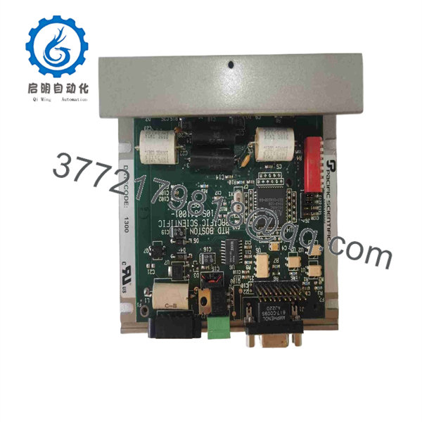
6410-009-N-N-N
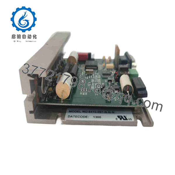
6410-009-N-N-N
Stage 3 — Installing the New Module
Estimated time: 20–30 minutes
- Compare the replacement label with the removed unit.
- Confirm 6410-009-N-N-N.
- Verify that the replacement configuration does not include a heat sink.
- Check the available cabinet airflow and mounting orientation.
- Verify the motor’s rated phase current.
- Set the drive’s current-selection switches according to the motor and applicable 6410 documentation.
- Match all approved configuration switches to the original installation.
- Mount the drive securely.
- Reconnect:
- DC power
- Motor phases
- Step/direction or applicable command signals
- Grounding connections
- Perform a polarity and continuity check before energizing.
⚠️ Do not blindly copy DIP-switch settings. A switch setting that was correct for the old motor may be wrong for a replacement motor. Verify the motor’s rated current and required microstep resolution.
The 6410-009-N-N-N uses separate power, signal, and motor connectors; available technical listings identify a 3-contact power terminal, 9-socket D-sub signal connector, and 5-contact motor terminal.
Stage 4 — Power-On & Testing
Estimated time: 30–60 minutes
- With power isolated, check the DC input for accidental shorts.
- Verify supply polarity.
- Confirm the DC supply is within the 24–75 VDC operating range.
- Energize the drive with the machine in a controlled state.
- Check for fault indications or abnormal current behavior.
- Apply a low-frequency step command.
- Confirm correct motor phase sequence and rotation direction.
- Check for:
- Excessive vibration
- Audible resonance
- Missed steps
- Unexpected heating
- Unstable positioning
- Increase command frequency progressively.
- Test acceleration and deceleration under controlled load.
- Verify commanded and actual mechanical positions.
- Record final current settings, supply voltage, microstep configuration, and test results.
⚠️ The drive can power up normally while still having incorrect phase wiring or current configuration. Do not release the machine for production until the axis has passed its required positioning and load tests.
For incoming QC, record the exact part number and physical condition, inspect connectors, verify the DC supply range, check motor-phase behavior, confirm configuration settings, and retain test evidence. Secondary-market suppliers currently list new, unused, and refurbished versions, so the physical condition and test status should be confirmed for each individual unit.
Frequently Asked Questions (FAQ)
1. What is the Pacific Scientific 6410-009-N-N-N?
It is a 6410-series digital microstepping stepper drive designed for controlling two-phase stepper motors. Its documented electrical range is 24–75 VDC with up to 5.0 A RMS phase current.
2. What is the maximum output current?
The specified maximum phase current is 5.0 A RMS, with a reported peak phase current of 7.1 A. The actual operating current must be configured according to the connected motor.
3. What is the maximum step frequency?
The 6410-009-N-N-N supports up to 2.0 MHz step frequency when the digital input filter is disabled. The reported minimum step pulse under this condition is 250 ns.
4. Does 6410-009-N-N-N include a heat sink?
No. Available product specifications identify the heat sink option as not included. Cabinet airflow and the 60 °C maximum chassis temperature therefore need to be considered during installation.
5. What connectors are used?
The documented configuration includes a 3-contact plug-in screw terminal for power, a 5-contact plug-in screw terminal for the motor, and a 9-socket D-sub miniature connector for logic signals.
6. Is the 6410-009-N-N-N still manufactured?
The model is treated as a legacy/discontinued industrial drive in secondary-market listings. Replacement, repair, refurbished, and unused units can still be sourced, but availability and condition vary.
7. Can another Pacific Scientific 6410 model replace it directly?
Not automatically. Other 6410 models can have different option codes, covers, heat sinks, connectors, or application configurations. The complete 6410-009-N-N-N code should be matched before approving a replacement.



