
 WhatsApp: +86 16626708626
 Email:
  Phone: +86 16626708626
Description
Key Technical Specifications
| Parameter | Specification |
|---|---|
| Manufacturer | Parker SSD Drives / Parker Hannifin |
| Part Number | 8903-AI-00 |
| Product Family | AC890 |
| Option Designation | 8903/AI |
| Product Type | High-resolution analog input and encoder option card |
| Analog Input | 1 differential input |
| Analog Input Range | ±10 V |
| Analog Resolution | 15 bits + sign |
| Analog Input Impedance | 100 kΩ |
| Analog Low-Pass Filter | 3 kHz |
| Encoder Channels | A, B, Z |
| Encoder Input Type | Optically isolated differential |
| Encoder Compatibility | RS422 / RS485 |
| Encoder Input Voltage | ±30 V differential; 0–30 V single-ended |
| Maximum Encoder Pulse Rate | 250 kHz |
| Encoder Receiver Current | ≤10 mA per channel |
| Synthesized Encoder Output | 3 differential digital outputs |
| Encoder Output Frequency | Up to 250 kHz per output |
| Output Current | ±100 mA per output |
| Encoder Supply | 30 V |
| Operating Encoder Supply | 5–24 V |
| Maximum Cable Length | 150 m |
| Compatible Drives | 890SD and 890CD |
| Firmware Compatibility | Version 2.5 onward / Version 3.5 onward |
| Version 20.X Compatibility | Not compatible |
Parker’s product manual specifies the analog channel as a differential ±10 V input with 15-bit plus sign resolution and 100 kΩ input impedance. The same option provides optically isolated differential A, B, and Z encoder inputs and three differential outputs for synthesized encoder signals.
The encoder interface supports RS422/RS485-type signals as well as higher-voltage encoder outputs. Parker specifies a maximum encoder pulse rate of 250 kHz, with a maximum cable length of 150 m under the documented conditions.
Product Introduction
The Parker 8903-AI-00 is the AC890 high-resolution analog input option used to add a precision analog reference to compatible 890 drives. The additional input can be used as a normal configuration input or directly as a high-speed speed setpoint, making the card suitable for applications where an AC890 drive must follow a precision analog command from a CNC or another motion controller.
The option also incorporates incremental encoder feedback and synthesized encoder output. Its 15-bit-plus-sign analog resolution, differential ±10 V input, 250 kHz encoder capability, and RS422/RS485 compatibility make the exact option useful in coordinated speed and position-control applications. Parker specifies the 8903/AI for 890SD and 890CD drives.
Installation & Configuration Guide
Stage 1 — Pre-Installation Preparation
Estimated time: 15–20 minutes
- Notify operations and place the AC890 drive in a controlled maintenance state.
- Apply LOTO to the drive and motor power circuit.
- Isolate the control supply as required by the applicable AC890 installation procedure.
- Wait at least 5 minutes for the drive DC bus capacitors to discharge, then verify the DC bus voltage with a properly rated meter.
- Wear an ESD wrist strap before handling the option card.
- Prepare a PH1 screwdriver, multimeter, wire labels, smartphone/camera, and the current AC890 configuration file.
- Photograph the existing drive, option-card position, encoder wiring, and analog-reference wiring.
- Record the installed firmware version.
- Confirm that the drive is an 890SD or 890CD and that the required firmware is compatible with the 8903/AI option. Parker states that the option is not compatible with Version 20.X firmware.
⚠️ Do not install the card simply because it physically fits the drive. Verify the model, firmware version, option position, encoder arrangement, and application configuration first.
Stage 2 — Removing the Old Module
Estimated time: 10–15 minutes
- Confirm the drive DC bus is discharged using the approved measurement procedure.
- Label all analog and encoder conductors before disconnection.
- Photograph the terminal arrangement and shield connections.
- Disconnect the encoder A, B, and Z wiring where applicable.
- Disconnect the analog reference wiring.
- Release the option-card retaining hardware.
- Remove the existing option card straight from its connector.
- Inspect the mating connector and surrounding PCB area for contamination, bent contacts, or signs of overheating.
- Retain the removed card until the replacement passes commissioning.
Stage 3 — Installing the New Module
Estimated time: 15–20 minutes
- Verify the replacement is 8903-AI-00 / 8903/AI.
- Check the card for physical damage and verify its identification label.
- Align the option card with the designated interface.
- Seat the card evenly without applying excessive force.
- Secure the card using the applicable retaining hardware.
- Reconnect the differential analog input.
- Reconnect encoder A, B, and Z signals according to the original wiring documentation.
- Verify encoder supply voltage and signal polarity.
- Check cable shielding and grounding against the drive installation requirements.
- Verify that the analog input is configured for the intended ±10 V signal range.
⚠️ Do not assume a single-ended encoder wiring scheme is equivalent to the documented differential interface. The 8903/AI encoder inputs are designed around differential signaling, with additional support for specified RS422/RS485 and voltage-output arrangements.
Stage 4 — Power-On & Testing
Estimated time: 20–40 minutes
- Before energizing, check for shorts between the applicable control and signal conductors.
- Restore power according to the startup procedure.
- Confirm the drive recognizes the installed option.
- Verify the configured firmware is supported by the 8903/AI.
- Apply a known analog reference and confirm the drive reads the expected value.
- Test the analog signal at zero, mid-scale, and positive/negative limits as appropriate.
- Verify encoder A/B phase relationship and Z-pulse operation.
- Confirm the synthesized encoder output if it is used by the CNC or motion controller.
- Check speed-reference scaling and direction before enabling the motor.
- Perform a controlled low-speed test before returning the machine to production.
Troubleshooting note: If the analog reference is unstable, check differential wiring, signal grounding, shield termination, input scaling, and the 3 kHz input filter characteristics. If encoder feedback is incorrect, check A/B phase, Z-channel wiring, encoder supply, signal amplitude, and maximum-frequency requirements before replacing the option card.
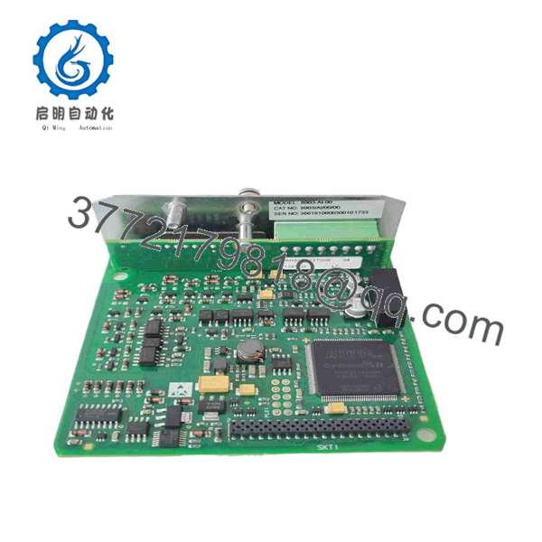
8903-AI-00
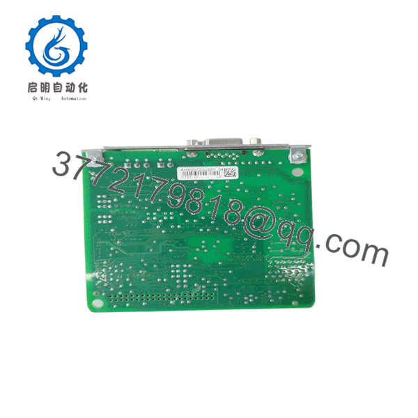
8903-AI-00
Frequently Asked Questions (FAQ)
1. What is Parker 8903-AI-00?
8903-AI-00 is the Parker high-resolution analog input option card. It adds a precision analog input and also provides incremental encoder input and synthesized encoder output.
2. What analog signal does 8903-AI-00 accept?
The analog channel is a differential ±10 V input with 15 bits + sign resolution and a 100 kΩ input impedance. Parker specifies a 3 kHz low-pass filter for the analog input.
3. Does 8903-AI-00 include an encoder interface?
Yes. The 8903/AI combines the high-resolution analog input with an incremental encoder interface. It provides A, B, and Z differential inputs and synthesized encoder outputs.
4. Which Parker drives support 8903-AI-00?
Parker documentation specifies the option for 890SD Standalone Drives and 890CD Common Bus Drives.
5. What firmware versions are compatible?
Parker’s manual specifies compatibility with Version 2.5 onward and Version 3.5 onward, while explicitly stating that the option is not compatible with Version 20.X. Always verify the actual firmware installed in the drive before commissioning.
6. What is the maximum encoder frequency?
The documented maximum encoder pulse rate is 250 kHz. Parker also specifies up to 250 kHz on each synthesized encoder output and a maximum cable length of 150 m under the specified installation conditions.
7. Is 8903-AI-00 the same as 8903/AI?
Yes. 8903-AI-00 is the not-fitted ordering code for the Parker 8903/AI high-resolution analog input option. Parker’s manual explicitly lists these as the product order code and option designation.



