
 WhatsApp: +86 16626708626
 Email:
  Phone: +86 16626708626
Description
Key Technical Specifications
- Parameter: Manufacturer — Parker
- Parameter: Part Number — CPAR-04AE-13574
- Parameter: Alternate Marking — CP*AR-04AE-13574 / CP-AR-04AE-13574
- Parameter: Product Category — Servo driver / inverter-related assembly
- Parameter: Application — Industrial motion-control equipment
- Parameter: Technology Family — Parker Compumotor
- Parameter: Electrical Input — Not reliably established from the available public documentation
- Parameter: Motor Output Rating — Not reliably established
- Parameter: Output Current — Not reliably established
- Parameter: Communication Interface — Not reliably established
- Parameter: Dimensions — Verify from the physical unit
- Parameter: Weight — Verify from the physical unit
- Parameter: Operating Temperature — Verify against the applicable Parker manual
- Parameter: Installation — Machine/control cabinet installation; exact mounting arrangement must be verified
A Japanese industrial-equipment service record lists Parker CP*AR-04AE-13574 as a driver, and another equipment record associates the same part number with an inspection machine. A supplier listing also describes it as a Parker servo-related product.
Important: I would not publish a voltage, horsepower, current, encoder interface, or dimensional specification for this part without the nameplate or Parker documentation. The available web records are inventory references rather than a Parker datasheet, and some listings contain conflicting product descriptions.
Product Introduction
The Parker CPAR-04AE-13574 is a legacy Parker industrial motion-control component identified in available equipment records as a driver. It appears in Parker/Compumotor spare-parts inventories and has also been associated with inspection-machine equipment.
For replacement work, the complete CPAR-04AE-13574 designation should be matched against the existing unit’s nameplate, connector layout, electrical ratings, and machine documentation. Because publicly indexed specifications are incomplete, do not substitute another Parker AR-series component solely because the housing or prefix appears similar.
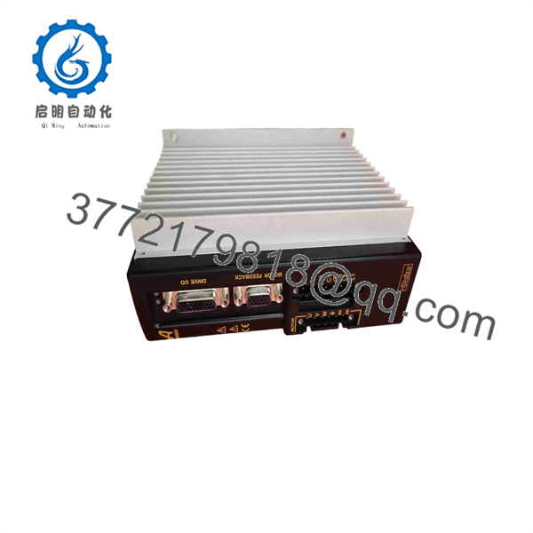
CPAR-04AE-13574
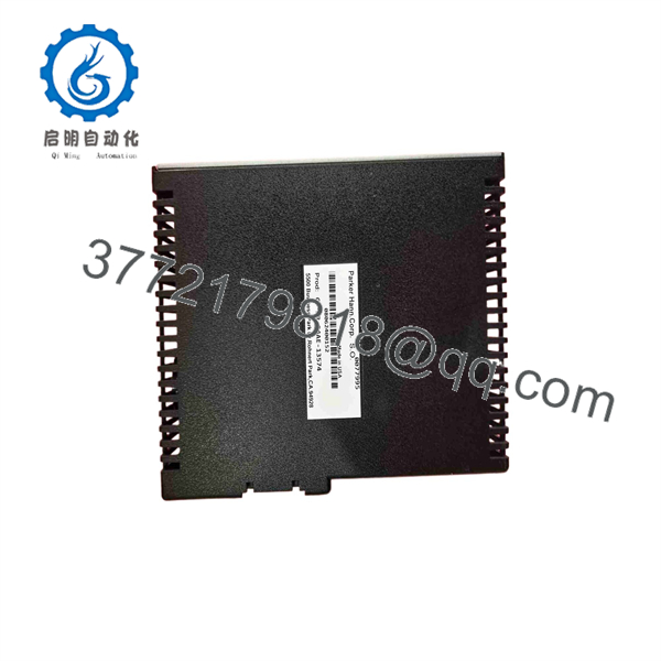
CPAR-04AE-13574
Installation & Configuration Guide
Stage 1: Pre-Installation Preparation — Approx. 10 Minutes
⚠️ Safety First
- Notify operations and place the machine in an approved safe state.
- Apply lockout/tagout (LOTO) to the applicable electrical supply.
- Wait at least 5 minutes before accessing the drive assembly.
- Verify the DC bus and incoming supply are discharged with an appropriately rated multimeter.
- Follow the machine OEM’s electrical safety procedure if it specifies a longer discharge period.
Tools Required
- ESD wrist strap
- PH1/appropriate cabinet screwdriver
- Digital multimeter
- Wire labels
- Smartphone or camera
- Torque screwdriver where the machine documentation specifies terminal torque
Data Backup
Before removing the existing CPAR-04AE-13574:
- Photograph the complete nameplate.
- Photograph every connector and terminal.
- Photograph DIP switches, jumpers, rotary switches, and adjustment potentiometers.
- Record the drive’s existing parameter settings where accessible.
- Record motor model, encoder/resolver information, and controller configuration.
- Photograph cable routing.
❗ Do not assume the CPAR-04AE-13574 has the same electrical configuration as another Parker drive with a similar prefix.
Stage 2: Removing the Old Module — Approx. 5 Minutes
- Remove the cabinet cover or protective guard.
- Label every cable before disconnecting it.
- Disconnect control, feedback, and motor connections according to the machine wiring diagram.
- Do not pull on cable conductors or connector bodies with excessive force.
- Release the mounting hardware.
- Remove the CPAR-04AE-13574 without stressing adjacent wiring.
- Inspect the mounting surface, connectors, and surrounding wiring for heat damage, contamination, or loose terminals.
Keep the original unit until the replacement has completed commissioning.
Stage 3: Installing the New Module — Approx. 5–10 Minutes
- Put on the ESD wrist strap.
- Verify the replacement marking is exactly .
- Compare connector positions and mechanical dimensions with the removed unit.
- Transfer documented switches, jumpers, and adjustable settings exactly.
- Install the replacement in the original mounting position.
- Secure the mounting hardware.
- Reconnect control and feedback wiring using the photographs and wiring diagram.
- Reconnect motor wiring only after verifying the terminal identification.
- Check cable shielding and grounding against the machine documentation.
- Perform a final mechanical inspection before applying power.
Self-Checklist
- Exact part number verified
- Nameplate photographed
- Connector arrangement matches
- Switch/jumper settings copied
- Motor wiring verified
- Feedback wiring verified
- Ground/shield connections verified
- Mounting hardware secured
Stage 4: Power-On & Testing — Approx. 10–20 Minutes
- Check for shorts before energizing the drive.
- Verify the incoming supply against the machine’s electrical drawing.
- Power the control system with the motor mechanically safe.
- Observe the drive’s status indicators.
- Check for immediate fault indications.
- Verify controller-to-drive communication if the installation uses a digital interface.
- Confirm motor and feedback identification.
- Restore documented parameters only after confirming that the replacement hardware is compatible.
- Enable the axis at low speed or under a controlled test condition.
- Verify direction, feedback polarity, limits, stop behavior, and commanded motion.
- Run a controlled production test before returning the machine to service.
⚠️ If the drive immediately reports an overcurrent, feedback, or configuration fault, stop the test. Do not repeatedly reset the fault. Check motor wiring, feedback wiring, parameter compatibility, and the exact replacement hardware.
Technical Pitfall & Survival Guide
❗ Firmware / Hardware Revision
Do not assume that a visually identical legacy Parker unit has identical firmware or internal configuration. Record the revision information from the original before replacement.
❗ Configuration Switches
Take photographs before removing the old unit. On legacy motion equipment, a single switch or jumper can change an operating parameter. Copy the physical configuration rather than relying on memory.
❗ Motor and Feedback Wiring
This is where replacement jobs can become expensive. Verify every motor and feedback terminal against the machine drawing. Do not wire from another Parker drive’s pinout simply because the connector looks identical.
❗ Power Rating
The exact electrical rating for should be verified from the unit nameplate or OEM documentation before energizing. The public listings located for this part do not provide sufficiently reliable voltage/current data.
❗ ESD
Use a grounded wrist strap and ESD-safe work surface when handling the electronics. Avoid touching exposed circuit-board contacts.
Frequently Asked Questions (FAQ)
Q1. What is Parker ?
Available industrial-equipment records identify , while supplier catalogs associate it with Parker/Compumotor servo equipment. One service database also lists it specifically as a driver.
Q2. Is a current Parker product?
It appears to be a legacy Parker component. The part number is primarily found in industrial spare-parts and equipment-service listings rather than current mainstream Parker product documentation. For a critical machine, verify availability and replacement status with Parker or an authorized technical source before redesigning the system.
Q3. Can I replace it with another Parker AR-series unit?
Not automatically. A similar Parker prefix does not establish electrical or functional compatibility. Compare the complete part number, motor rating, feedback system, connector configuration, control interface, and machine application before substitution.
Q4. What condition should I specify when purchasing?
Specify one of these conditions explicitly:
- New Original / New Surplus
- Factory Sealed
- Refurbished / Tested
For a legacy , request photographs of the actual unit, including its nameplate and revision markings. Do not treat a generic catalog photograph as proof of condition.
Q5. Can be hot-swapped?
Do not assume it can. The available references do not establish a Parker-approved hot-swap procedure for this exact part number. Unless the machine documentation explicitly permits energized replacement, isolate power and follow the machine LOTO procedure.
Q6. Will replacing the driver erase the machine program?
The answer depends on the machine architecture. The motor drive and the machine controller can store different portions of the configuration. Before replacement, back up controller programs and document the driver’s parameters. Do not assume that replacing the physical drive will automatically restore its previous settings.
Q7. What information should I provide when ordering a replacement?
Provide the complete part number, a clear nameplate photograph, hardware/revision markings, machine or equipment model, motor model, feedback type, and photographs of all connectors. This information is particularly important here because publicly available documentation does not establish the complete electrical specification with sufficient confidence.
For this part, I would verify the physical nameplate before publishing exact voltage, current, motor-power, or dimensional specifications. That avoids turning an uncertain reseller listing into a false technical specification.



