
 WhatsApp: +86 16626708626
 Email:
  Phone: +86 16626708626
Description
Key Technical Specifications
| Parameter | Value |
|---|---|
| Manufacturer | Parker SSD Parvex |
| Model | DLD13004R |
| Product Family | DIGIVEX / DLD |
| Product Type | Digital AC servo amplifier / position-control drive |
| Nominal Drive Power | 750 W |
| Approximate Horsepower | 1.02 HP |
| Input Supply | 230 V AC |
| Input Phase | Three-phase |
| Input Frequency | 47–63 Hz |
| Input Current | 3.8 A |
| Continuous Output Current | 4 A |
| Peak Output Current | 8 A |
| Output Voltage Range | 0–310 V AC |
| Output Frequency Range | 0–1,000 Hz |
| Regenerative Power Rating | 60 W |
| Typical Application | Servo positioning, speed control, and torque control |
| Compatible Motor Requirement | Match Parvex motor voltage, feedback type, brake wiring, and commissioning parameters |
| Lifecycle Status | Discontinued by manufacturer / legacy spare part |
| Fieldbus and I/O Options | Verify from the exact label, connector set, and installed configuration |
| Enclosure / Environmental Rating | Verify from the actual unit and original Parvex documentation before installation |
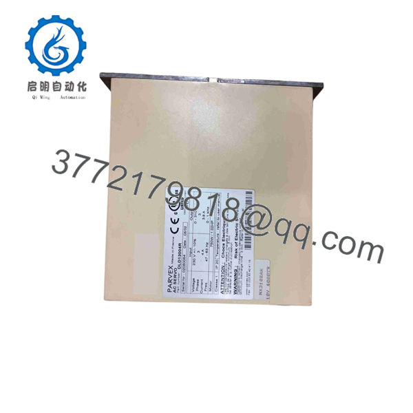
Available product references consistently identify the DLD13004R as a discontinued Parker SSD Parvex digital servo drive rated for three-phase 230 V AC input, 4 A continuous output, 8 A peak output, 0–310 V AC motor output, 0–1,000 Hz output frequency, and 750 W power class.
Product Introduction
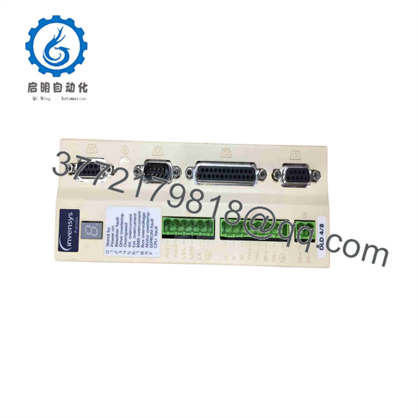
The Parker SSD Parvex DLD13004R is a 750 W DIGIVEX-series digital AC servo drive used for precision position, speed, and torque control of compatible Parvex servo motors. It accepts 230 V AC three-phase input and supplies variable-frequency motor output up to 310 V AC. Typical applications include packaging machinery, machine tools, converting equipment, robotics, indexing systems, and automated assembly equipment.
The DLD13004R is a legacy, configuration-sensitive drive. Match the motor nameplate, feedback device, resolver or encoder wiring, brake circuit, command interface, parameter backup, and regeneration arrangement before replacement. The correct base model alone does not prove that the spare contains the same firmware or application configuration.
DLD13004R
DLD13004R
Troubleshooting Quick Reference
| Symptom | Possible Cause | Relevance to This Part | Quick Check Method | Recommendation |
|---|---|---|---|---|
| Drive display or status LEDs remain off | Missing three-phase supply, missing auxiliary control supply if fitted, blown fuse, open isolator, loose connector, failed internal power supply | ✅ High | With qualified personnel and safe procedures, measure phase-to-phase voltage at the drive input. Verify upstream fuses, disconnect switch, contactor status, and control-power connections from the machine schematic. | Correct incoming power faults before replacing DLD13004R. Do not assume the drive is defective just because it is dark. |
| Drive powers up but does not enable | Emergency stop active, servo-enable signal missing, safety relay open, PLC inhibit, external fault active, parameter interlock | ❌ Usually low | Read the drive fault display or diagnostic output. Check the machine enable chain, safety relay contacts, controller command, and drive-ready signal. | Check external enable conditions before replacing the servo drive. Most no-enable faults originate outside the amplifier. |
| Motor hums but will not rotate | Motor brake remains engaged, jammed mechanics, missing phase, incorrect motor cable, feedback fault, wrong motor parameters | ⚠️ Medium | Isolate power. Confirm the axis moves freely by approved mechanical methods. Check brake release voltage, motor cable continuity, feedback connector seating, and motor nameplate data. | Repair brake, mechanical, cable, or feedback faults first. Do not repeatedly command torque into a locked axis. |
| Motor moves in the wrong direction after drive replacement | Parameter mismatch, reversed command polarity, feedback configuration mismatch, motor phase sequence error | ✅ Medium | Stop motion safely. Compare old and replacement drive parameters, motor data, feedback wiring, and axis direction settings. Perform a low-speed controlled jog with travel limits active. | Restore the approved parameter file. Do not swap motor phases or feedback wires by trial and error. |
| Drive trips on overcurrent during acceleration | Mechanical binding, excessive acceleration, motor cable short, motor winding issue, incorrect current limits, failed output stage | ⚠️ Medium | Check mechanical load and commanded acceleration. With power isolated, inspect motor cable and measure motor insulation only using the motor manufacturer’s approved procedure. Compare motor current with the 4 A continuous and 8 A peak drive ratings. | Correct the mechanical or wiring fault. If the overcurrent persists with a verified motor and cable, the output stage may require repair or replacement. |
| Drive trips during deceleration | Regeneration energy exceeds capacity, braking resistor issue, rapid deceleration profile, high reflected inertia | ⚠️ Medium | Review the fault code, deceleration rate, load inertia, and regeneration wiring. Confirm the application’s regeneration method and any external resistor condition. | Reduce deceleration demand or correct the regeneration circuit. The DLD13004R is listed with a 60 W regeneration rating; verify the machine’s exact braking arrangement. |
| Drive overheats after several minutes | Blocked ventilation, failed internal fan, high cabinet temperature, sustained overload, contaminated heatsink | ✅ High | Inspect fan operation, cooling path, cabinet filters, and clearance around the drive. Trend motor current during normal operation. | Correct airflow and loading first. A drive that repeatedly overheats under a verified load may need repair. |
| Position error or unstable servo motion | Resolver/encoder issue, loose feedback connector, shield problem, parameter corruption, mechanical backlash | ⚠️ Medium | Inspect feedback cable shielding and connector retention. Compare the drive’s position feedback diagnostics with commanded movement. Check whether the same symptom remains with a known-good motor or cable. | Verify feedback wiring and restore the approved tuning/parameter set before replacing the drive. |
| Drive communicates incorrectly with machine controller | Wrong command-interface configuration, bad cable, missing reference signal, incompatible firmware, incorrect PLC configuration | ⚠️ Medium | Identify the actual command interface from the connectors and machine drawings. Check cable continuity, shield grounding, reference voltage, and controller diagnostics. | Do not assume one configuration matches another. Confirm the interface and firmware from the old unit. |
| Replacement unit faults immediately | Incorrect firmware, parameter mismatch, wrong motor feedback type, incompatible connector configuration, wiring error, ESD damage | ✅ High | Photograph and compare the old and new labels, connectors, option cards, motor and feedback wiring, and any stored parameter data. | Stop commissioning until the unit matches the original configuration. Order using the complete nameplate and application details. |
| Motor output appears present but axis remains stationary | Brake not releasing, coupling failure, gearbox issue, sheared key, mechanical disconnect | ❌ Low | Check brake coil voltage and mechanical coupling with the machine safely isolated. Observe motor shaft movement versus driven load movement. | Investigate mechanics before replacing the drive. This symptom often comes from a failed brake or coupling, not the amplifier. |
❗ High-voltage warning: The accepts three-phase 230 V AC and produces motor output up to 310 V AC. Disconnect and lock out incoming power, wait for internal capacitors to discharge according to OEM requirements, and verify absence of hazardous voltage with a properly rated meter before handling terminals or motor connectors.
❗ Feedback warning: Take clear photos before removal. Record the motor label, feedback connector, resolver or encoder cable, brake wiring, command interface, and every drive label. I have seen a replacement servo drive blamed for a fault when the real problem was one partially seated resolver connector after a midnight motor change.
If the fault remains unresolved, provide technical support with the full label, all diagnostic codes, motor nameplate, command-interface photos, feedback-cable photos, parameter backup, input-voltage readings, and motor-current measurements.
Frequently Asked Questions
What is the Parker SSD Parvex ?
The is a Parker SSD Parvex DIGIVEX-series digital AC servo drive. It controls a compatible servo motor for position, speed, and torque applications. Product references list it as a 750 W, three-phase 230 V AC drive with 4 A continuous output and 8 A peak output.
What are the electrical ratings of ?
Available listings identify a 230 V AC three-phase, 47–63 Hz input; 3.8 A input current; 0–310 V AC output; 0–1,000 Hz output frequency; 4 A continuous output current; and 8 A peak output current. Confirm the physical nameplate before installation because legacy drives may have revision-specific details.
Is a 750 W servo drive?
Yes. Multiple sources list the as a 750 W position-control or servo-amplifier module. One source also lists the equivalent class as approximately 1.02 HP.
Is obsolete?
Yes. It should be treated as a discontinued legacy drive. A distributor listing explicitly marks it as discontinued by the manufacturer, so current availability depends on verified surplus, refurbished, repair-exchange, or used inventory.
Can I replace with another 230 V, 750 W servo drive?
No, not without engineering work. Servo drives are not interchangeable based only on voltage and power. You must match the motor winding voltage, current rating, feedback type, brake voltage, feedback connector pinout, control interface, firmware, tuning parameters, machine safety circuit, and regeneration method. A generic 750 W drive will not necessarily recognize or control an existing Parvex motor.
Can I hot-swap this drive?
No. Do not remove or install a while energized. It carries hazardous AC input and motor output voltage, stores energy internally, and connects to equipment that can move without warning. Follow lockout/tagout, allow capacitor discharge time, verify voltage, and secure the machine axis before replacement.
Will I lose the machine program if I replace the ?
The machine PLC or CNC program normally remains in its controller, not in the servo amplifier. However, drive-specific data can be critical: motor parameters, current limits, tuning values, command scaling, feedback configuration, and fault settings may reside in the drive or in the commissioning environment. Back up parameters before removal whenever the old drive can still communicate.
Why is a New Surplus less expensive than a current Parker drive?
New Surplus stock often comes from machine-builder spares, canceled projects, unused maintenance inventory, distributor overstock, or equipment decommissioning. The lower price usually reflects obsolescence and the limited market for a legacy configuration. Ask for exact-unit label photos, connector photos, condition details, firmware information where available, functional test evidence, warranty terms, and return conditions.
What testing should a supplier perform before shipping a refurbished ?
A credible evaluation should include visual inspection for corrosion, damaged terminals, heat damage, rework evidence, and connector wear; label documentation; controlled power-up; status and fault-display checks; cooling-fan verification; a compatible motor run test; feedback verification; current monitoring under load; and a documented burn-in period. For a drive with a known command interface, request an interface check as well. Bench testing does not replace final commissioning with the installed motor, feedback hardware, machine mechanics, safety chain, and parameter set.



