
 WhatsApp: +86 16626708626
 Email:
  Phone: +86 16626708626
Description
Key Technical Specifications
| Parameter | Value |
|---|---|
| Manufacturer | Parker Hannifin |
| Model Number | J1005000 |
| Product Category | Motion control module |
| Application | Industrial automation and machine motion systems |
| Controller Family | Parker legacy motion control platform |
| Input Voltage | Verify from OEM documentation/nameplate |
| Communication Interface | Configuration dependent |
| Programming Software | Configuration dependent |
| I/O Capability | Configuration dependent |
| Mounting Type | Industrial control cabinet mounting |
| Operating Temperature | Verify exact hardware revision |
| Firmware | Revision dependent |
| Replacement Method | Exact model and revision matching required |
⚠️ Technical identification note: The designation J1005000 alone is not enough to confirm electrical compatibility. Parker legacy equipment often uses additional suffixes, firmware revisions, and system-specific modules. Always compare the complete label, installed firmware, connector layout, and machine drawings before installation.
Product Introduction
The Parker J1005000 is a legacy industrial automation module used in Parker motion-control systems. It is designed for machine control applications requiring coordinated motion, actuator control, and integration with industrial automation equipment.
For replacement projects, the critical factor is matching the complete hardware configuration rather than the base model number alone. Engineers should verify connector pinouts, firmware revision, communication method, and installed application parameters before returning the machine to service.
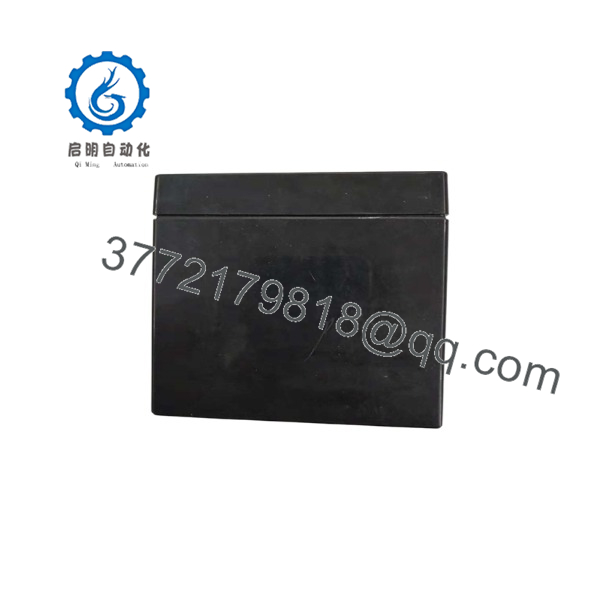
J1005000
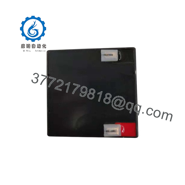
J1005000
Installation & Configuration Guide
Stage 1: Pre-Installation Preparation — 10 minutes
⚠️ Safety First
- Notify production personnel about the maintenance window.
- Place the machine into a safe operating state.
- Apply lockout/tagout procedures.
- Remove control power.
- Wait for stored energy discharge according to the machine documentation.
- Verify supply voltage absence with a calibrated multimeter.
Tools Required
- ESD wrist strap
- PH1 screwdriver
- Digital multimeter
- Wire labels
- Smartphone for reference photos
- Torque screwdriver
Data Backup
- Photograph the complete J1005000 nameplate.
- Record firmware/version information.
- Photograph all terminal wiring.
- Document communication addresses and parameters.
- Save PLC/motion configuration files if available.
- Record DIP switch or jumper settings.
Stage 2: Removing the Old Module — 5–10 minutes
- Remove the cabinet access cover.
- Confirm power isolation.
- Label every connector before removal.
- Disconnect communication cables carefully.
- Remove terminal blocks without pulling wires.
- Release mounting hardware.
- Remove the module straight from the rack or mounting surface.
- Inspect connectors for corrosion, bent pins, or contamination.
⚠️ Keep the original module until the replacement has completed functional testing. The old hardware is often the fastest reference for configuration recovery.
Stage 3: Installing the New Module — 10 minutes
- Wear an ESD wrist strap.
- Confirm the replacement matches the original J1005000 identification.
- Compare connector locations and terminal assignments.
- Transfer DIP switch and jumper settings.
Configuration Clone (Critical)
- Match node addresses.
- Match communication parameters.
- Match I/O configuration.
- Match motion parameters.
- Verify encoder or feedback settings if applicable.
- Install the module into the correct mounting position.
- Secure mounting hardware.
- Reconnect wiring using the original photographs.
- Confirm all connectors are fully seated.
Self-Checklist
- Correct model verified
- Firmware checked
- Wiring matched
- Communication settings copied
- Grounding verified
- Mounting secured
Stage 4: Power-On & Testing — 15 minutes
- Perform a visual inspection.
- Check power supply voltage before energizing.
- Power the control system.
- Observe diagnostic LEDs.
- Connect Parker programming software if applicable.
- Verify module recognition.
- Load saved configuration if required.
- Test communication with the PLC or host controller.
- Perform low-speed axis testing.
- Verify limits, feedback, and fault response.
⚠️ Troubleshooting Note
- No communication: Check address settings, cable type, and protocol configuration.
- Module fault: Verify firmware compatibility and parameter files.
- Motion error: Confirm feedback wiring and motor configuration.
- Unexpected behavior: Compare the replacement configuration against the original backup.
Frequently Asked Questions (FAQ)
Can I hot-swap the Parker J1005000?
No. Unless the specific Parker system manual explicitly defines hot-swap capability, remove power before replacement. Most legacy motion modules are not designed for live insertion or removal.
Is the Parker obsolete?
The is considered a legacy industrial automation part. Availability usually comes from remaining inventory, surplus stock, or tested refurbished sources. Confirm the supplied condition before purchase.
Is a complete ordering number?
Not always. Legacy Parker products frequently require additional identification from the equipment label, firmware revision, and installed system configuration. Provide photographs of the complete label when requesting a replacement.
Will my motion program be lost when replacing the module?
It depends on where the application parameters and motion program are stored. Before removal, back up controller files and document all configuration parameters. Do not assume a replacement module contains your machine settings.
Can I replace the with a newer Parker controller?
Possibly, but it is not normally a direct plug-in replacement. A migration requires checking I/O mapping, communication protocols, software compatibility, mechanical fit, and commissioning requirements.
Why is surplus pricing lower than OEM pricing?
Legacy automation components are commonly sourced from machine decommissioning projects, inventory liquidation, and repair stock. Price differences usually reflect availability and condition. A New Original/New Surplus unit, tested refurbished unit, and used unit should be evaluated separately.
What information should I provide before ordering a replacement?
Provide:
- Complete model label photo
- System model
- Firmware revision
- Connector photographs
- Application type
- Existing controller configuration
These details prevent receiving a similar-looking module with incompatible hardware or firmware.



