
 WhatsApp: +86 16626708626
 Email:
  Phone: +86 16626708626
Description
Key Technical Specifications
| Parameter | Value |
|---|---|
| Case Size | 1/16 DIN |
| Input Types | Thermocouple, RTD, linear DC mV/mA, digital input |
| Output | Latching limit relay (up to 5 A per documented 1161 variants) — output count/type varies by ordering suffix |
| Communication | RS485, selectable MODBUS or ASCII protocol |
| Display | Dual 4-digit display |
| Supply Voltage | 100–240 VAC, 50/60 Hz (optional 20–48 VAC/VDC configurations available) |
| Operating Temperature | 32°F to 131°F (0°C to 55°C) |
| Storage Temperature | -4°F to 176°F (-20°C to 80°C) |
| Humidity | 20% to 95% RH, non-condensing |
| Ingress Protection | IP66 |
| Safety Function | Latches on limit trip — cannot be reset until process returns to a safe operating condition |
| Approvals | FM approved; UL/CE listed (per Partlow documentation for the 1161+ family) |
| Warranty | 3-year manufacturer warranty (current Partlow terms) |
⚠️ Cross-check the specific relay count, output type, and input sensor configuration for your exact P6702 suffix against the Partlow 1161+ configuration guide — the base “P6702” designation covers multiple wired configurations under this numbering scheme, similar to how the current catalog uses the “P1161xxxxxx” format.
Product Introduction
The Partlow P6702 is a 1/16 DIN limit controller from the 1161+ Series — not a standard PID process controller, but a dedicated safety device that shuts a process down when it exceeds a preset temperature threshold and stays latched off until the process returns to a safe condition and an operator manually resets it. It accepts thermocouple, RTD, linear DC mV/mA, or digital inputs, and communicates over RS485 using selectable MODBUS or ASCII protocol.
What earns this a spot on an oven, furnace, or thermal-forming line over a general-purpose controller is exactly that fail-safe behavior: it can’t be talked into ignoring an over-temperature condition by an operator in a hurry. Jumperless input configuration and auto-hardware recognition on the 1161+ generation cut setup time meaningfully versus older Partlow limit controllers, and FM approval matters directly if your process falls under NFPA 86 or similar combustion-safety requirements for ovens and furnaces.
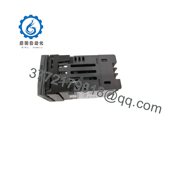
P6702
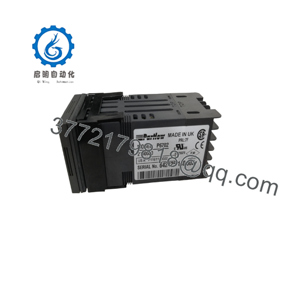
P6702
Installation & Configuration Guide
Stage 1: Pre-Installation Preparation (~10 min)
⚠️ Safety First: Notify operations of the downtime window, verify the process is in a safe state, lock out/tag out the panel power feeding the controller, and confirm no residual voltage on the terminal block with a multimeter before disconnecting wiring.
Tools Required: ESD strap, small flathead/Phillips screwdriver for terminal screws, multimeter, wire labels, smartphone for reference photos.
Data Backup: Document the existing configuration — input sensor type, limit setpoint, relay output wiring, and MODBUS address/baud rate if networked. Photograph the terminal block wiring before disconnecting anything, since 1/16 DIN limit controllers pack a lot of terminals into a small rear panel.
Stage 2: Removing the Old Module (~5 min)
- Remove power to the controller at the panel breaker or disconnect.
- Label and disconnect all terminal wiring — input sensor leads, relay output wiring, supply voltage, and any RS485 communication leads.
- Release the mounting bracket/clips on the rear of the 1/16 DIN housing and slide the controller out of the panel cutout from the front.
- Inspect the panel cutout and gasket area for damage before installing the replacement.
⚠️ Keep the old unit available until the replacement is confirmed operating correctly — its configuration settings are your primary reference if the replacement doesn’t ship pre-configured to match.
Stage 3: Installing the New Module (~15 min)
- Confirm the replacement is genuinely a P6702 with a matching configuration suffix — input type, output configuration, and supply voltage must match your application; a mismatched input type (e.g., RTD ordered where a thermocouple was configured) won’t read correctly even though the housing and panel cutout are identical.
- Configuration clone (critical): Re-enter the documented limit setpoint, input sensor type, and MODBUS address/baud rate settings using the front-panel HMI or the Windows PC configuration software.
- Slide the controller into the panel cutout and secure the rear mounting clips.
- Reattach all terminal wiring per your labels — input sensor, output relay, supply voltage, and communication leads.
Self-Checklist: [ ] Input sensor type confirmed [ ] Limit setpoint re-entered [ ] Wiring reattached per labels [ ] Mounting clips secured
Stage 4: Power-On & Testing (~10 min)
Pre-Power Check: Multimeter check across the supply terminals for shorts before re-energizing.
- Power up the controller and confirm the dual 4-digit display initializes correctly.
- Verify the input reading tracks a known reference temperature or test signal.
- Confirm the limit setpoint matches your documented value and that the latching relay trips at the correct threshold during a controlled test.
- Test the manual reset function — confirm the unit will NOT reset while the simulated process condition remains above the limit threshold.
- If networked, confirm MODBUS/ASCII communication with the host system before returning the line to production.
⚠️ Troubleshooting Note: If the display shows an input fault or out-of-range reading immediately after installation, check the input sensor type configuration first — a controller ordered with the wrong sensor type (thermocouple vs. RTD) is a far more common cause of an immediate fault than a wiring error, since these units require correct type selection to interpret the incoming signal.
Frequently Asked Questions (FAQ)
Can the Partlow P6702 be hot-swapped under power?
No. This is a panel-mount instrument wired directly to line voltage and process I/O — de-energize the circuit and confirm zero voltage at the terminals before disconnecting or installing the unit.
Is the P6702 obsolete, and is “new” stock genuinely new?
Partlow continues to sell the 1161+ limit controller family under current West Control Solutions branding, so this isn’t formally discontinued — but confirm current lead time, since older “”-numbered stock (a legacy part-numbering convention) may be sourced through distributor inventory rather than a fresh factory run under the current “P1161” numbering scheme. Ask for date code and packing list verification on any unit sold as new.
What’s the direct replacement if this exact suffix is out of stock?
Partlow’s current catalog uses the “P1161” prefix (e.g., P1161100000) for the same 1161+ limit controller family — cross-reference your suffix against Partlow’s configuration guide to find the equivalent current part number with matching input type, output configuration, and supply voltage.
Will I lose my limit setpoint and configuration when I swap the unit?
Yes, unless documented beforehand. The limit setpoint, input sensor type, and communication settings are stored in the unit itself — there’s no external configuration media on this platform. Record your settings from the old controller (or via the Windows PC configuration software, if you’ve used it previously) before removal.
Why does this limit controller “latch” instead of just resetting automatically like a normal thermostat?
That’s not a bug — it’s the entire point of a limit controller. Once the process exceeds the preset limit, the relay latches off and stays off even after the temperature drops, requiring a manual reset once the process is confirmed safe. If you need a standard controller that cycles output based on setpoint without latching, you want a Partlow process controller (like the P1160/P1610 series), not a limit controller.
Why is your price lower than Partlow’s list price?
Distributor and secondary-market pricing on an instrument like this typically reflects overhead differences rather than a lesser product — state plainly whether the specific unit is factory-sealed new stock, distributor new-old-stock, or refurbished-and-tested, along with date code, before quoting a customer.



