
 WhatsApp: +86 16626708626
 Email:
  Phone: +86 16626708626
Description
3. Key Technical Specifications
| Parameter | Value |
|---|---|
| Order Number | 2952855 |
| Nominal Input Voltage (UN) | 230 V AC (50/60 Hz) |
| Typical Input Current | Approx. 5 mA |
| Contact Configuration | 1 PDT (Single Pole Double Throw / SPDT) |
| Contact Material | AgNi (Silver-Nickel) |
| Max. Switching Voltage | 250 V AC / DC |
| Limiting Continuous Current | 6 A |
| Connection Method | Screw Connection (M3 thread) |
| Conductor Cross-Section | 0.2 mm² to 2.5 mm² (24 to 14 AWG) |
| Mounting Position / Type | Any / DIN rail mounting (NS 35/7,5 or NS 32) |
| Dimensions (W x H x D) | 22.5 mm x 75.0 mm x 62.5 mm |
| Operating Temperature Range | −20 °C to +50 °C |
4. Product Introduction
The Phoenix Contact EMG 22-REL/KSR-230/21 (2952855) is an industrial electromechanical relay interface module engineered for signal coupling, electrical isolation, and level matching between high-voltage field equipment and lower-level PLC system circuits. Housed in a compact 22.5 mm wide DIN-rail enclosure, it operates on a 230 V AC nominal coil voltage and features an integrated status LED alongside a freewheeling/rectifier protective circuit.
This module is widely specified across legacy process automation facilities due to its integrated screw terminal blocks, clear protective cover, and mechanical isolation barrier. The AgNi contact arrangement provides reliable switching characteristics up to 6 A, making it a rugged interface option where solid-state outputs lack the necessary galvanic isolation or voltage ratings.
5. S.O.P. Quality Control & Testing Transparency
Every EMG 22-REL/KSR-230/21 unit processed through our warehouse undergoes rigorous verification before dispatch to ensure zero out-of-box field failures.
Step 1: Inbound Inspection & Traceability
- Source Audit: OEM packing lists and customs documentation verified against serial batches.
- Visual & Structural Inspection: Module housing checked under high magnification for terminal corrosion, housing cracks, UV degradation, or broken mounting foot springs.
- Accessory Verification: Checks for terminal screw integrity, marker labels, and intact transparent housing covers.
Step 2: Live Electrical & Functional Testing
- Bench Setup: Unit mounted on a standard NS 35/7.5 DIN rail powered by a regulated AC supply source.
- Power-On & LED Test: 230 V AC applied to terminals A1/A2 to confirm activation threshold, crisp mechanical click, and correct LED illuminated state.
- Contact Resistance Test: Contact resistance measured across closed contacts (terminals 11 to 14) using a Fluke 115 multimeter, ensuring values remain below 50 mΩ.
- Load Testing: Continuous power applied for 4 hours at maximum operating temperature ratings while checking for coil heat dissipation anomaly.
Step 3: Electrical Parameter & Insulation Testing
- Insulation Resistance: 500 V Megger test applied between the input coil circuit and output switching contacts to verify galvanic separation exceeding 10 MΩ.
- Dielectric Test: High-potential test to confirm dielectric strength between coil and contact set matches factory limits (4 kV AC, 1 minute).
Step 4: Packaging & ESD Final Prep
- Final QC Sign-off: Test sheet generated and archived with serial/batch logs.
- Protective Packaging: Unit vacuum sealed in moisture-barrier anti-static packaging, wrapped in heavy-duty 3/16″ bubble layer, and packed in reinforced double-wall corrugated boxing.
- Verification Guarantee: Full test videos and resistance log photos available upon request prior to shipment.
6. Technical Pitfall & Survival Guide
1. Coil Voltage Rating Violations (AC vs. DC)
- Issue: Supplying 230 V DC to this module’s 230 V AC coil will burn out the internal coil winding rapidly due to the lack of inductive reactance.
- Avoidance: Always verify whether your control loop outputs 230 V AC or 230 V DC. If running on 24 V DC or 110 V AC, select the corresponding EMG 22 variant (e.g., KSR-24/21).
2. Contact Inductive Arc Pitfalls
- Issue: Switching unsuppressed inductive loads (such as large solenoid valves or brake coils) direct from the AgNi contact causes heavy contact pitting, welding the contacts together over time.
- Avoidance: Install an external RC snubber network or varistor directly across the external inductive AC load.
- Field Warning: “I’ve logged calls where techs replaced three of these modules back-to-back in a week. They thought the relays were defective, but the real culprit was an unsuppressed 230 V AC hydraulic valve drawing massive inductive kickback. Add a varistor across your valve terminals.”
3. Terminal Torque Missteps
- Issue: Stripping internal cage clamps or leaving terminals loose creates localized high resistance, melting the 22.5 mm plastic shell.
- Avoidance: Use a properly sized PH1 or 0.6 x 3.5 mm flathead screwdriver. Torque terminal screws strictly between 0.5 and 0.6 Nm (4.4 to 5.3 lb-in).
4. Mixed Voltage Isolation Clearance
- Issue: Running 230 V AC switching voltage alongside 24 V DC sensor feedback lines through adjacent terminals without proper isolation barriers violates panel layout regulations.
- Avoidance: Route high-voltage AC field lines away from low-voltage DC control lines in trunking channels. Maintain physical separation along the terminal block edge.
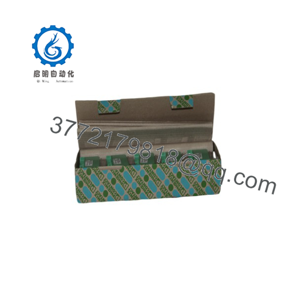
EMG 22-REL/KSR-230/21
7. Installation & Configuration Guide
Stage 1: Pre-Installation Preparation (Est. Time: 5 Mins)
- Safety Lockout: Disconnect main 230 V AC power feeds supplying the control panel section. Follow LOTO protocols and verify zero voltage on wire leads using an AC multimeter.
- Required Tools: Screwdriver (0.6 x 3.5 mm flathead), multimeter, wire strippers, ferrule crimper, wrist strap.
- Data Audit: Photograph existing wiring connections to document terminal assignments (A1/A2 coil input, 11 common, 12 NC, 14 NO).
Stage 2: Removing the Faulty Module (Est. Time: 5 Mins)
- Power down the panel sub-rack completely.
- Carefully loosen screw terminals on the top and bottom of the old module and pull wire ferrules straight out. Label each wire clearly.
- Insert a flathead screwdriver into the green DIN rail locking tab clip at the bottom of the unit.
- Pry the clip downward slightly to unlatch it from the DIN rail and pull the module off the rail forward.
Stage 3: Physical Installation of New Unit (Est. Time: 5 Mins)
- Inspect the rear DIN clip mechanism on the new EMG 22 module for smooth spring movement.
- Hook the upper mounting recess of the module onto the top edge of the DIN rail (NS 35 or NS 32).
- Press the lower half firmly against the rail until the metal mounting foot snaps into place with a clear click.
- Connect wiring using wire ferrules according to your field diagram:
1
Wire Coil Connections
Input Control Circuit
1.Wire Coil Connections:Input Control Circuit.
Insert 230V AC neutral and switched hot lines into terminals A2 and A1 respectively. Torque screw to 0.5 Nm.
2
Wire Contact Output
Switched Field Circuit
2.Wire Contact Output:Switched Field Circuit.
Attach Common feed to terminal 11. Connect Normally Closed loop to terminal 12 or Normally Open output to terminal 14.
3
Physical Tug Test
Mechanical Reliability Check
3.Physical Tug Test:Mechanical Reliability Check.
Gently pull on each wire to confirm the terminal cage clamp has gripped the ferrule tightly without pinching insulation.
Stage 4: Power-On & Live Commissioning (Est. Time: 10 Mins)
- Re-apply 230 V AC control power to the circuit feeding terminal A1.
- Verify the integrated yellow LED lights up brightly when coil voltage is applied.
- Measure AC/DC voltage across output terminals 11 and 14 using a multimeter to confirm contact closure.
- Cycle control signal 3 to 5 times under no-load and full-load conditions to ensure clean relay pick-up and drop-out times (typically < 8 ms drop-out, < 9 ms pick-up).
8. Frequently Asked Questions (FAQ)
Q: Is the Phoenix Contact EMG 22-REL/KSR-230/21 hot-swappable under load? A: No. You must de-energize the circuit before removal or installation. Pulling a live screw-terminal module carrying 230 V AC creates an arcing risk that can damage adjacent components or shock panel technicians. Always kill power to the A1/A2 and switching circuits first.
Q: What is the direct replacement if this specific part number (2952855) is out of stock? A: Modern installations typically migrate to the RIFLINE Complete series or PLC-INTERFACE series, such as the PLC-RSC-230UC/21 (Order No. 2966605). However, note that newer slimline modules are 6.2 mm wide compared to the 22.5 mm width of the EMG series. If cabinet layout relies on the physical footprint or specific screw layout of the EMG series, using an exact-match replacement prevents wire length and DIN rail spacing issues.
Q: Can I use this relay to switch low-current 24 V DC PLC inputs? A: It is not ideal for very low currents (under 10 mA). The silver-nickel (AgNi) contacts in this module rely on a small switching arc to burn off oxidation. Switching ultra-low current micro-signals through AgNi contacts over time leads to unreliable continuity. For low-level PLC inputs, select a relay with gold-plated (AgNi + Au) contacts.
Q: Why does your unit show “New Surplus” rather than current factory production? A: Many legacy EMG series modules are discontinued or maintained on extended lead-time production by Phoenix Contact. We source genuine, unused, factory-sealed modules from verified global system integration inventory overstock. They undergo full bench and insulation testing before sale to guarantee original factory operation.
Q: Will I lose any programming or configuration parameters when swapping this module? A: None at all. This is a purely electromechanical hardware interface module. It contains no microprocessor, firmware, or volatile memory. Once installed and wired according to the terminal pinout diagram, it works instantly without software configuration.



