
 WhatsApp: +86 16626708626
 Email:
  Phone: +86 16626708626
Description
Key Technical Specifications
- Parameter: Model Number: 301131
- Parameter: Product Designation: PSS SB BRIDGE
- Parameter: Manufacturer: Pilz
- Parameter: Product Series: PSS 3000 SafetyBUS p
- Parameter: Product Type: SafetyBUS p bridge and interface module
- Parameter: Primary Function: Connects or bridges SafetyBUS p network sections
- Parameter: Network: SafetyBUS p
- Parameter: Nominal Supply Voltage: 24 V DC
- Parameter: Nominal Current Consumption: 90 mA
- Parameter: Nominal Power Consumption: 2.2 W
- Parameter: Device Role: Distributed safety-network infrastructure; not a standard digital I/O module
- Parameter: Configuration Dependency: Requires compatible PSS/SafetyBUS p controller, topology, system software, and validated safety application
- Parameter: Safety Logic Dependency: Safety behavior depends on the controller project, standard function blocks, network configuration, wiring, and final validation
- Parameter: Installation Requirement: Panel-mounted or system-integrated installation in an approved SafetyBUS p architecture
- Parameter: Lifecycle Status: Legacy PSS 3000 / SafetyBUS p hardware; confirm actual stock, firmware revision, and migration path before ordering
Pilz identifies the 301131 as the PSS SB BRIDGE, a bridge used in SafetyBUS p systems. Public product data lists 24 V DC supply, 90 mA current consumption, and 2.2 W power consumption. Some listings incorrectly call it a digital I/O module; it is a SafetyBUS p network bridge/interface component, not a 16-point input card.
Product Introduction
The Pilz 301131 PSS SB BRIDGE is a SafetyBUS p bridge module for Pilz PSS safety automation systems. It connects SafetyBUS p network sections so that distributed safety controllers, remote safety I/O, and other approved network devices can exchange safety-related communication within the validated system architecture.
This is infrastructure hardware, not a standard field-input or relay-output card. A failed or incorrectly configured bridge can affect communications for an entire remote safety station or network segment. Before replacement, document the existing bus topology, bridge revision, cable routing, controller diagnostics, termination settings, and safety project version. The correct physical installation matters as much as the correct part number.
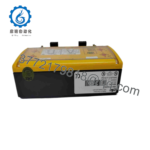
301131
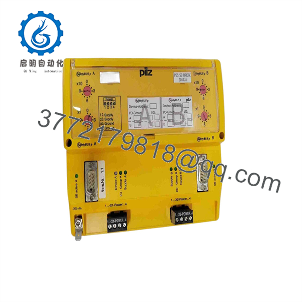
301131
Troubleshooting Quick Reference
| Symptom | Possible Cause | Relevance to This Part | Quick Check Method | Recommendation |
|---|---|---|---|---|
| PSS SB BRIDGE has no LEDs or status indication | Missing 24 V DC supply, blown fuse, reversed polarity, loose supply terminal, failed bridge | ✅ High | Measure 24 V DC and 0 V directly at the bridge supply terminals using a calibrated multimeter. Check upstream fuse, power supply status, and adjacent module power. | Restore a stable power supply before replacing the 301131. Do not condemn the bridge without confirming voltage under load. |
| SafetyBUS p communication fault appears after replacement | Incorrect bridge installation, wrong bus connector orientation, missing termination, project/topology mismatch, loose connector | ✅ High | Compare the physical network arrangement with pre-removal photos and the approved SafetyBUS p topology drawing. Inspect connectors, cable strain relief, and terminating resistor settings. | Restore the original topology and termination. Revalidate the safety project before attempting to restart the machine. |
| Remote safety I/O station is offline | Broken SafetyBUS p cable, disconnected bridge, missing 24 V DC at station, failed remote I/O station, controller fault | ✅ Medium | Check whether the controller sees any devices beyond the bridge. Inspect both bridge-side connectors, measure station power, and verify cable continuity with the system isolated. | Repair cable, power, or station faults first. Replace the 301131 only if the failure remains localized to a known-good bridge position. |
| Intermittent bus faults during machine vibration | Loose connector, damaged cable shield, poor strain relief, vibration-induced terminal movement, power-supply dropout | ✅ Medium | Review diagnostic timestamps and compare faults with machine cycles. Inspect cable clamps, connector latches, cabinet vibration, and 24 V DC stability. | Secure and replace damaged cabling. Do not solve an intermittent network issue by forcing resets or ignoring safety diagnostics. |
| System will not leave safe state after bridge replacement | Safety project mismatch, network node not recognized, controller not reset, external safety input still open, output feedback fault | ❌ Low | Confirm the bridge is recognized in diagnostics, then trace the safety sequence from inputs through controller logic, outputs, and feedback loops. | Do not replace a healthy bridge for an input, program, or output-side safety condition. |
| Communication fault affects only devices after the bridge | Bridge hardware fault, downstream cable fault, termination error, voltage drop at remote segment | ✅ High | Compare diagnostics for devices before and after the bridge. Test the bridge position with a known-good unit only under approved change control. | If upstream devices remain healthy and all downstream nodes fail with verified cabling and supply, the 301131 is a credible replacement candidate. |
| Duplicate or unexpected device diagnostics | Wrong project loaded, bridge revision mismatch, topology changed, undocumented previous modification | ✅ Medium | Check controller project version, device inventory, physical bus drawing, and installed bridge identification label. | Restore the validated project and physical topology. Do not commission a changed safety network without formal validation. |
| Bus fault after panel maintenance | Connector disturbed, shield disconnected, terminating resistor changed, cable crushed, earth connection loosened | ✅ Medium | Inspect every touched connector and cable path. Compare resistor/termination positions with the approved drawing. | Repair the installation error before replacing hardware. Network faults immediately after maintenance are often mechanical. |
| Module feels warm or has discoloration | Excessive ambient temperature, poor panel ventilation, supply fault, internal failure, nearby heat source | ✅ Medium | Check cabinet temperature, 24 V DC supply stability, and visible signs of heat on terminals or housing. | Correct the thermal or power condition. Replace the bridge if heat damage is visible or it fails in a verified environment. |
| Entire safety system is offline | Safety controller fault, common 24 V DC power failure, SafetyBUS p master issue, main cable break, emergency-stop condition | ❌ Low | Check controller LEDs, system power, master bus status, and whether multiple independent segments are unavailable. | Diagnose the safety controller and common infrastructure before replacing one bridge module. |
❗ Do not confuse the 301131 with the Pilz 301130 PSS SB DI16. The 301130 is a 16-input safety I/O module; the 301131 PSS SB BRIDGE is a SafetyBUS p communication bridge. The parts serve completely different functions.
❗ Photograph the bus topology before removal. Capture every connector, cable direction, screen/earth treatment, module position, termination setting, power terminal, and device label. I have seen a valid replacement remain “faulty” for hours because the downstream SafetyBUS p connector was installed in the wrong direction and the termination setting was not restored.
❗ Do not move or alter termination settings casually. A terminating resistor belongs at defined points in the network, not wherever it happens to make a fault LED disappear. Incorrect termination can cause unstable communication that appears only during production vibration or electrical noise.
❗ Do not bypass a SafetyBUS p network fault. If the system entered a safe state due to lost safety communication, find and repair the communication problem. Forcing outputs or bypassing diagnostics defeats the reason the safety network exists.
If you are stuck, provide technical support with photos of the 301131 label and revision, bridge LEDs, power terminals, both SafetyBUS p connectors, cable routing, termination setting, controller diagnostics, network topology drawing, and safety project version. Keep these checks in mind and you will save yourself 90% of typical rework time.
Frequently Asked Questions (FAQ)
What is the Pilz 301131 PSS SB BRIDGE used for?
The Pilz 301131, designated PSS SB BRIDGE, is a bridge component for SafetyBUS p systems. It connects SafetyBUS p network sections within a Pilz PSS safety automation architecture, allowing communication between approved distributed safety devices and controllers.
Is the 301131 a safety input or output module?
No. It is not a standard digital-input or relay-output module. It is a SafetyBUS p communication bridge/interface module. Some reseller listings use broad labels such as “safety I/O module,” but the Pilz product description identifies it as a bus connector/bridge component for SafetyBUS p.
What supply does the PSS SB BRIDGE require?
Public product information lists a 24 V DC supply, 90 mA current consumption, and 2.2 W power consumption. Confirm the exact wiring and permitted supply range from the Pilz manual for the installed revision before energizing the replacement.
Can I use the 301131 in a standard Ethernet or Profibus network?
No. The 301131 is designed for Pilz SafetyBUS p systems. It is not a general-purpose Ethernet switch, Modbus gateway, Profibus repeater, or unmanaged network bridge. Use only within a compatible Pilz PSS/SafetyBUS p design and the validated safety project.
Can I hot-swap the Pilz 301131?
Do not assume hot swapping is permitted. Removing a SafetyBUS p bridge can make downstream safety devices unavailable and place the machine in a safe state. Follow the machine’s approved lockout, change-control, safety validation, and return-to-service procedure before servicing it.
Why does the safety system show a bus fault after I replace the bridge?
The usual causes are a disturbed connector, wrong cable routing, missing or misplaced termination, incorrect project/topology configuration, 24 V DC supply loss, damaged downstream cable, or an offline remote station. Start with the physical network and controller diagnostics. The bridge should be replaced only after power and cabling are verified.
Will replacing the 301131 erase the safety program?
The safety project normally resides in the Pilz controller or engineering system, not in the bridge module. But a replacement can still create a topology mismatch or communication fault if its revision, placement, network connection, or termination does not match the validated installation. Back up the safety project and document the network before removal.
Is the 301131 obsolete, and should I keep a spare?
Treat the PSS 3000 SafetyBUS p platform as legacy hardware and verify current availability with Pilz or a qualified supplier. If the bridge supports a critical remote safety I/O segment, keep an exact matching spare and preserve the bus drawing, module revision, safety project, termination record, wiring photos, and validation procedure.



