WhatsApp: +86 16626708626
 Email:
 Phone: +86 16626708626
Description
Core Product Summary (Brand / Model / Key Attributes)
The Pilz PSS SB DI8O8 (Order Number 301140) is a decentralized digital input/output module engineered for integration within Pilz SafetyBUS p safety networks. It operates as a failsafe fieldbus node, receiving input states from safety switches and field sensors while controlling output actuators driven by a SafetyBUS p-compatible Programmable Safety System (PSS) master controller.
The module features 8 digital inputs, 8 digital outputs (6 positive-switching and 2 negative-switching rated at 2 A each), and 2 dedicated test pulse outputs for short-circuit detection across external wiring. Operating on a 24 V DC system supply with galvanic isolation from the SafetyBUS p bus, the unit supports single- and dual-channel safety-related input configurations. The housing features status LEDs for every input and output channel alongside an adjustable rotary switch for establishing SafetyBUS p bus addresses.
Key Technical Specifications
| Parameter | Verified Specification Value |
| Manufacturer & Order Number | Pilz PSS SB DI8O8 (301140) |
| Product Type | Decentralized Digital Input/Output Module |
| Fieldbus Protocol | SafetyBUS p |
| Digital Inputs | 8 failsafe digital inputs (24 V DC) |
| Digital Outputs | 8 digital outputs (6 positive-switching, 2 negative-switching) |
| Output Current Rating | 2 A per output channel |
| Test Pulse Outputs | 2 dedicated pulse outputs (T_0, T_1) for wiring monitoring |
| Module Power Supply (“Supply”) | 24 V DC (feeds electronics and test pulse outputs) |
| Load Power Supply (“Load Supply”) | 24 V DC (feeds output loads) |
| Bus Galvanic Isolation | Optocoupler isolation from SafetyBUS p |
| Maximum Output Capacitance | Up to 1 µF for positive-switching outputs |
| Internal Output Resistance | 0.35 \Omega |
| Status Indicators | Yellow LEDs for inputs; Green LEDs for outputs |
| Operating Temperature | 0°C to 60°C |
Detailed Product Overview
The Pilz PSS SB DI8O8 serves as a remote I/O node in distributed functional safety architectures. Communicating over the SafetyBUS p protocol, the module offloads local safety sensor wiring from central control cabinets while maintaining real-time diagnostic reporting back to a main PSS safety CPU.
The module’s 8 digital inputs accept single-channel or dual-channel safety devices, including E-stop pushbuttons, safety light curtains, interlocking guards, and two-hand controls. When paired with the 2 integral test pulse outputs, the module actively tests external input circuits for cross-circuits, earth faults, and shorted signal lines. Input signal filtering ignores transient noise pulses below 500 µs to prevent nuisance trips.
On the actuation side, the module manages 8 high-current outputs rated at 2 A each. The 6 positive-switching outputs are designed to drive resistive, inductive, and capacitive loads up to 1 µF. The 2 negative-switching outputs allow dual-pole switching combinations when paired with positive-switching channels. Automated internal diagnostic routines test output channel integrity periodically, guaranteeing rapid fault recognition and shutdown in the event of short-circuit, overload, or thermal fault conditions.
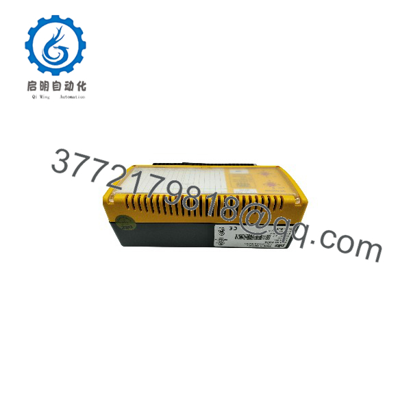
PSS SB DI8O8
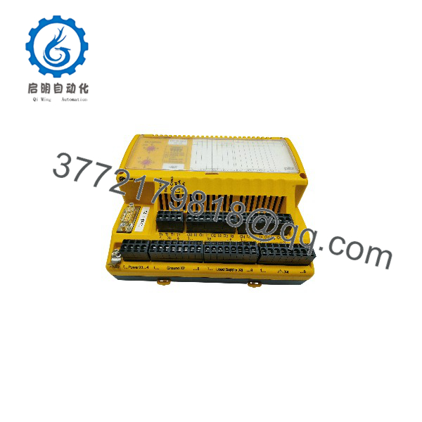
PSS SB DI8O8
Engineering Selection Highlights
- SafetyBUS p Integration: Communicates safety-critical input and output data directly over a SafetyBUS p line, reducing multi-core field wiring runs.
- Cross-Circuit Monitoring: Integrated test pulse generators (T_0, T_1) detect short circuits between input lines without requiring external testing hardware.
- High Output Drive Capacity: 2 A per output channel provides sufficient current to directly energize heavy contactors, solenoids, and safety actuators.
- Dual 24 V DC Power Rails: Separate “Supply” and “Load Supply” terminals allow independent power isolation for logic/sensors versus output actuator loads.
- Logical I/O Grouping: Inputs and outputs can be assigned to up to 2 distinct logical SafetyBUS p groups for zone-based emergency stop and safety control.
Dimensions, Mounting & Connection Notes
The PSS SB DI8O8 is housed in an industrial DIN-rail or panel-mountable enclosure with an approximate mass of 0.7 kg. Field connections use plug-in screw or spring-cage terminal blocks located along the front face of the unit.
The front panel houses status LEDs: yellow LEDs signal active input logic levels, while green LEDs reflect output energization status. When wiring capacitive loads to positive-switching outputs, ensure total circuit capacitance does not exceed 1 µF to prevent automated diagnostic test pulses (200 µs duration) from triggering unintentional load behavior or module faults.
System Compatibility & Integration Requirements
| Item / Dependency | Verified Compatibility or Requirement | Practical Note |
| Safety System CPU | SafetyBUS p-compatible Pilz PSS series controllers | Driven directly via SafetyBUS p telegrams. |
| Bus Addressing | Rotary address switch on module | Unique SafetyBUS p station address must be set prior to power-up. |
| Power Infrastructure | Two independent 24 V DC power sources with a common ground | One supply feeds logic/test pulses; the second supply feeds output loads. |
| Terminal Connections | Plug-in screw terminals or spring-loaded terminals | Allows quick replacement without unwiring field cables. |
| Fibre-Optic Bus Couplers | Compatible with Pilz PSS SB SUB-D FO modules | Allows conversion of SafetyBUS p electrical media to optical fiber links. |
FAQ
What is the Pilz PSS SB DI8O8?
The Pilz PSS SB DI8O8 (301140) is a decentralized digital input and output expansion module designed for use on SafetyBUS p industrial networks.
How many inputs and outputs does the PSS SB DI8O8 provide?
The module features 8 digital inputs, 8 digital outputs (6 positive-switching, 2 negative-switching), and 2 dedicated test pulse outputs.
What is the current rating for the digital outputs?
Each output channel is rated for a maximum load current of 2 A.
What is the purpose of the test pulse outputs on the module?
The dedicated test pulse outputs (T_0, T_1) generate test signals through connected safety sensors to detect short circuits, earth faults, and cross-wiring faults.
Does the module require separate power supplies?
Yes, the module requires two 24 V DC power connections sharing a common ground: one “Supply” for internal logic and test pulse outputs, and a separate “Load Supply” for output actuators.
Verification & Troubleshooting Notes
- Input LED Diagnostics: If a connected sensor is closed but the corresponding yellow input LED remains off, check that the 24 V DC “Supply” voltage is present at the input power terminals.
- I/O Group Stop Condition: When an output overload, short-circuit, or over-temperature condition occurs, the module automatically shuts off all outputs within the affected I/O group and enters a STOP state.
- Capacitive Load Faults: If positive-switching outputs shut down intermittently, verify that connected capacitive loads do not exceed 1 µF.
- Address Selection: Ensure the hardware rotary address switch on the unit matches the assigned station address configured in the system software.