
 WhatsApp: +86 16626708626
 Email:
  Phone: +86 16626708626
Description
Key Technical Specifications
- Manufacturer: Pioneer Magnetics
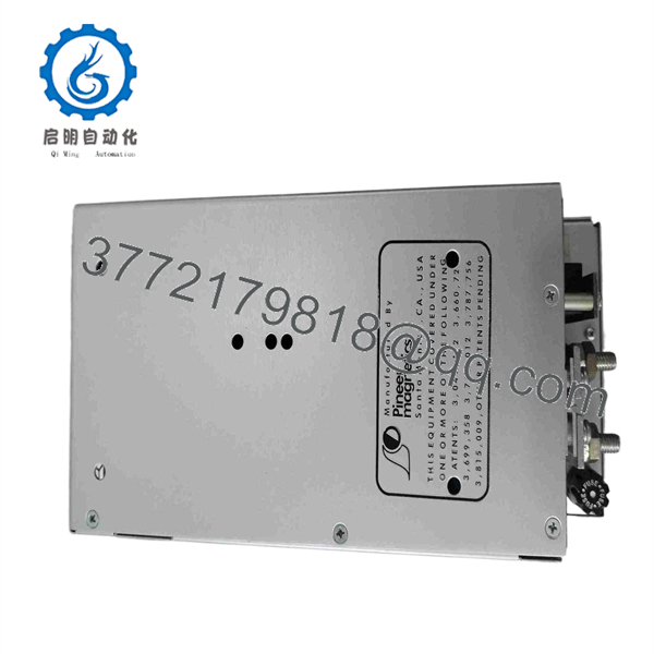
- Part Number: 24F33-0-4-R-S
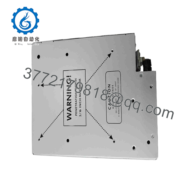
- Product Type: Switching DC/DC power supply module
- Output Configuration: Single regulated DC output
- Isolation: Isolated DC/DC converter architecture
- Monitoring: Power-fail signal/output reported by industrial spare-part references
- Installation Type: Legacy embedded or chassis-mounted power module; verify actual mounting and connector style from the installed unit
- Use Case: Conversion and regulation of DC power rails in legacy industrial control and embedded electronic equipment
- Redundancy/Parallel Use: Verify with the original system schematic; do not assume parallel operation is supported by this specific suffix
- Input Voltage: Verify from the physical nameplate or OEM system documentation before applying power
- Output Voltage: Verify from the physical nameplate, connected load requirements, and OEM schematic before replacement
- Output Current/Power Rating: Confirm from the unit label and equipment BOM; the part number alone is not adequate evidence for power-budget calculations
- Status: Discontinued / legacy power-conversion spare part
The available industrial references consistently identify the 24F33-0-4-R-S as a Pioneer Magnetics single-output switching DC/DC power supply module. Public pages do not provide a reliable original datasheet for its input range, output voltage, current rating, pinout, ripple specification, or mechanical dimensions. Do not energize or substitute this module until those values are verified from the original unit label and host-equipment drawings.
Product Introduction
The Pioneer Magnetics 24F33-0-4-R-S is a legacy single-output switching DC/DC power supply module used to generate a regulated, isolated DC rail in industrial and embedded control equipment. The module may also provide a power-fail signal used by host electronics to detect output loss or an out-of-regulation condition.
This is a replacement part where exact electrical and mechanical matching matters more than a broad product-family match. Before buying, verify the original module’s input range, output voltage, current rating, pin layout, connector style, enable/inhibit logic, power-fail signal polarity, and heat-sinking arrangement. Do not accept a claimed cross-reference without the supplier providing label and connector-side photographs.
Troubleshooting Quick Reference
| Symptom | Possible Cause | Relevance to This Part | Quick Check Method | Recommendation |
|---|---|---|---|---|
| Host equipment is completely dead | Upstream AC/DC supply failed, input fuse open, loose connector, failed DC/DC module | ⚠️ Medium | Measure the specified input DC voltage directly at the module input pins with a Fluke 115 or equivalent meter; check upstream fuses with power isolated | Confirm correct input voltage and polarity before replacing the module |
| Correct input voltage present but output is 0 V | Module failure, remote inhibit active, output short circuit, poor connector contact | ✅ High | Measure output at the module pins with the load disconnected if the OEM procedure permits; inspect enable/inhibit pin state from the schematic | Check for a downstream short first. A good converter can shut down under a shorted load |
| Output voltage is low or cycling | Overload, shorted daughterboard, high-resistance input connection, aging converter capacitors | ✅ High | Measure output at no load and under normal load; compare input voltage at the module during startup and use an oscilloscope to check output ripple if available | Isolate load branches. Replace the module only if voltage remains unstable with a known-good load |
| Power-fail alarm remains active | Incorrect power-fail wiring, wrong signal polarity, output out of tolerance, failed monitoring circuit | ✅ High | Compare power-fail pin voltage and logic state against the equipment schematic; verify output voltage at the same time | Do not jumper the alarm permanently. Identify whether the signal indicates module fault or external undervoltage |
| Module gets hot rapidly | Downstream overload, poor airflow, failed internal components, incorrect installation | ✅ High | Use a thermal camera or non-contact thermometer after a controlled power-up; measure output current and inspect ventilation path | Shut down if temperature rises abnormally. Verify load current and mounting heat transfer before installing another module |
| Output has excessive ripple or intermittent resets | Aged capacitors, poor grounding, connector oxidation, overload, switching-stage fault | ✅ High | Check ripple with an oscilloscope at the module output and at the load; inspect connector pins for oxidation or heat discoloration | Re-seat connectors and verify grounding. Replace the converter if ripple persists under a normal load |
| Replacement module does not fit or pinout differs | Revision mismatch, incorrect cross-reference, connector/keying variation | ✅ High | Compare all sides of the original and replacement: labels, terminal numbering, connector keyway, mounting holes, and heat-sink interface | Never force a connector or rely on a visually similar module. Return it if any pin or mechanical detail differs |
| New module fails immediately after installation | Reverse polarity, output short, incorrect input voltage, missing heat sink, wiring error | ✅ High | With power isolated, continuity-test output rails to return/ground and verify polarity from the schematic; photograph old wiring before removal | Correct the external fault before fitting another unit. Repeated replacements can destroy multiple modules |
❗ Do not assume an output fault means the Pioneer Magnetics module has failed. Downstream shorts, failed electrolytic capacitors on load boards, and high-resistance connectors are common causes. Record input voltage, output voltage, load current, ripple, and the power-fail signal state before removal. If you are stuck, send technical support photos of both labels, the connector face, the host-equipment schematic excerpt, and measured readings.
Frequently Asked Questions
What is the Pioneer Magnetics 24F33-0-4-R-S?
The Pioneer Magnetics 24F33-0-4-R-S is identified by industrial parts suppliers as a single-output switching DC/DC power supply module. It provides regulated DC power for legacy industrial or embedded electronic equipment, with references also describing an isolated output and power-fail signal.
What are the input and output voltage ratings?
Do not use a guessed rating. The public sources available for this part number do not provide a trustworthy OEM datasheet with the voltage range, output voltage, current capacity, or pinout. Read the original module label and check the host-system schematic or bill of materials. Applying the wrong input voltage or connecting an output rail incorrectly can damage the module and the downstream equipment.
Is 24F33-0-4-R-S a direct replacement for PM-2722-1 or Westinghouse 406A054H01?
One secondary-market listing claims that the 24F33-0-4-R-S, PM-2722-1, and Westinghouse 406A054H01 share form factor, pin allocation, and output ratings. Treat that statement as a lead for engineering verification, not proof of interchangeability. Compare original nameplate values, connector pinout, mounting dimensions, input polarity, output regulation, enable function, and power-fail logic before installing a cross-referenced unit.
Can I hot-swap this power supply module?
Do not assume it is hot-swappable. Many legacy DC/DC modules do not include controlled inrush, live-insertion sequencing, or connector contacts designed for powered removal. Isolate power, discharge stored energy as required by the equipment manual, and follow site lockout/tagout procedures before removal. Pulling a converter under load can arc connector pins and damage the host backplane or load circuitry.
Why does a replacement power module fail immediately after installation?
The original module may have failed because of an external problem that still exists: a shorted load, reverse polarity, wrong input voltage, a failed load-board capacitor, inadequate cooling, or an incorrectly wired enable/inhibit pin. Before installing the replacement, measure resistance from each output rail to return with power off, verify the input polarity, and inspect the connector for heat damage. Leave at least a 20% current margin between normal load and the verified converter rating.
Is this model obsolete, and is stock limited?
Yes, treat the 24F33-0-4-R-S as a legacy/discontinued power-conversion spare. Available supply is normally new surplus, used inventory, or refurbished stock from independent industrial-parts channels. Confirm physical stock, condition, lead time, and warranty in writing before issuing a purchase order.
Is New Surplus better than Refurbished for this module?
New Surplus is unused original inventory and is preferred when the unit has clean labels, sealed or well-preserved packaging, no corrosion, and documented storage history. Refurbished stock can also be appropriate when the supplier documents input/output verification, full-load operation, ripple measurement, thermal run testing, and warranty coverage. For either condition, request photos of every label and connector face, a written condition statement, and the test report.
What testing should a supplier perform before shipment?
For a New Original / New Surplus unit, request serial-number and label verification, visual inspection for corrosion or rework marks, inspection of pins and connector keying, and ESD-safe packaging. For a refurbished unit, request a controlled bench test using the correct input range and a representative resistive or electronic load. The report should document input voltage, no-load output, loaded output, output current, ripple/noise, power-fail signal behavior, thermal performance during an extended run, and final QC sign-off.



