
 WhatsApp: +86 16626708626
 Email:
  Phone: +86 16626708626
Description
Key Technical Specifications
| Parameter | Value |
|---|---|
| Model Number | F5-MEC-420 |
| Manufacturer | PMV, a Flowserve brand |
| Product Series | PMV F5 |
| Product Type | Valve position feedback unit / switch box |
| Primary Function | Continuous valve-position feedback and discrete open/close indication |
| Analog Output Signal | 4–20 mA, two-wire position transmitter |
| Transmitter Supply Voltage | 9–28 V DC; 24 V DC recommended |
| Output Current Limit | 24 mA DC |
| Maximum Loop Load | 800 Ω at 24 V DC |
| Analog Indication | LED indication at 4 mA ±1%; LED indication at 20 mA ±1% |
| Travel Range | Field selectable 30°, 45°, 60°, or 90° |
| Standard Maximum Travel | 90° |
| Direction Selection | Field selectable direct or reverse 4–20 mA action |
| Linearity | Less than 1% of full scale |
| Hysteresis | Less than 0.5% of full scale |
| Resolution | Essentially infinite |
| Mechanical Switches | Two mechanical SPDT V3 limit switches |
| Mechanical Switch Rating | 250 V AC, 6 A resistive / 2.5 A inductive |
| Mechanical Switch Approvals | CSA, UL, VDE |
| Mounting | Direct mount on PMV P5/EP5 positioners; VDI/VDE 3845 mounting |
| Enclosure Material | Die-cast aluminum with electrocoated finish |
| Environmental Protection | IP66 / NEMA 4 standard enclosure |
| Cable Entries | Two × 1/2 in. NPT or two × M20 × 1.5, configuration dependent |
| Terminals | Screw terminals up to 2.5 mm² / AWG 14 |
| Fasteners | Stainless steel A2/A4 |
| Operating Temperature | −40 to +80 °C for 4–20 mA transmitter version |
| Standard-Enclosure Weight | Approximately 0.7 kg / 1.5 lb |
The F5-MEC-420 is a feedback unit, not a pneumatic or digital valve positioner. It reports actual rotary actuator position to a PLC, DCS, or SIS through a 4–20 mA signal and provides mechanical limit-switch contacts. It mounts directly on PMV P5/EP5 analog positioners or can be installed using VDI/VDE 3845 hardware.
Product Introduction
The PMV F5-MEC-420 is a valve position feedback unit for quarter-turn pneumatic actuators and PMV P5 or EP5 analog positioners. It combines a two-wire 4–20 mA position transmitter with two mechanical SPDT limit switches, allowing a PLC, DCS, or safety system to see continuous valve travel while retaining discrete open and closed feedback contacts.
Use the F5-MEC-420 where a standard switch box is not enough. The transmitter supports field-selectable 30°, 45°, 60°, and 90° rotary travel, plus direct or reverse 4–20 mA action. Verify the mechanical actuator travel, cam alignment, mounting interface, and hazardous-area requirement before ordering.
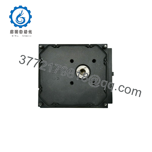
F5-MEC-420
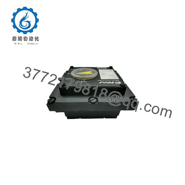
F5-MEC-420
Troubleshooting Quick Reference
| Symptom | Possible Cause | Relevance to This Part | Quick Check Method | Recommendation |
|---|---|---|---|---|
| 0 mA at the PLC or DCS analog input | Lost loop supply, open field wiring, reversed polarity, failed analog input fuse, transmitter failure | ❌ Low until loop power is confirmed | Measure DC loop voltage across the F5-MEC-420 transmitter terminals; confirm 9–28 V DC, with 24 V DC preferred; check continuity from field terminals to the marshalling cabinet | Restore loop power and repair wiring before replacing the feedback unit |
| Output remains at approximately 4 mA through full valve travel | Stuck shaft, loose coupling, wrong travel selector, failed transmitter, valve actuator not moving | ✅ Medium | Stroke the valve under approved operating conditions and observe output current with a calibrated loop meter; inspect coupling movement at the F5 input shaft | If the actuator shaft turns but current remains fixed, inspect the transmitter and internal coupling; replace if confirmed defective |
| Output remains at approximately 20 mA | Incorrect direct/reverse selection, travel beyond configured range, wiring short, transmitter fault | ✅ Medium | Confirm actual valve position, then measure loop current at closed, midstroke, and open; inspect direction-selection setting and travel configuration | Reconfigure only with the valve in a safe condition; verify 4 mA and 20 mA endpoints after adjustment |
| Signal increases when the valve closes | Direct/reverse output setting is wrong | ❌ Configuration issue | Stroke the actuator from closed to open while monitoring the analog signal; compare expected process logic with the measured direction | Set direct or reverse action as required, then document the final configuration |
| Output is unstable or jumps during travel | Loose linkage, cam backlash, actuator stiction, water ingress, wiring noise, failing potentiometer/transmitter mechanism | ✅ Medium | Trend mA signal while manually stroking the actuator; inspect mechanical coupling, shaft movement, enclosure seal, and cable shield termination | Correct mechanical backlash and wiring noise first; replace the unit if instability remains with a smooth actuator and clean signal loop |
| PLC reads 3.6 mA or less | Open loop, wiring break, transmitter supply below minimum, internal transmitter fault | ❌ Usually external | Check loop voltage at the field device and measure current directly in series; inspect terminals for loose conductors or corrosion | Correct the loop supply and field wiring before replacing the transmitter |
| PLC reads more than 21 mA | Shorted wiring, wrong supply connection, failed transmitter, input-card scaling issue | ✅ Medium | Measure current at the F5-MEC-420 output and separately at the PLC input; verify the loop supply is no more than 28 V DC | Isolate the field loop, correct wiring, and replace the feedback unit only if it independently drives excessive current |
| Open/closed limit switch never changes state | Cam misadjustment, actuator travel too short, loose internal cam, switch failure, incorrect terminal wiring | ✅ Medium | Use a meter to test each SPDT contact at the F5 terminals while slowly stroking the valve; observe cam actuation mechanically | Adjust cams to the actual end positions; replace the switch assembly if no contact change occurs with proper cam movement |
| Valve position signal is accurate but limit switches are wrong | Limit cams set incorrectly or switch contacts wired to wrong NO/NC terminal | ✅ High | Compare terminal wiring to the product manual and prove each switch’s common, NO, and NC contacts with a continuity test | Correct terminal selection and reset cams; do not alter the analog transmitter calibration unnecessarily |
| Limit switches work but analog position signal is wrong | 4–20 mA transmitter configuration, coupling slip, supply/load issue, transmitter failure | ✅ High | Confirm 9–28 V DC loop power, 800 Ω maximum load at 24 V DC, and shaft rotation; test 4 mA and 20 mA through a full stroke | Reconfigure the travel range and output direction; replace the transmitter unit if it cannot span correctly |
| Unit becomes intermittent after rain or washdown | Damaged cover gasket, loose conduit fitting, water ingress, damaged cable jacket | ✅ Medium | Isolate power, open the enclosure, inspect for moisture, corrosion, and contamination; check that unused conduit entries are plugged | Dry and correct sealing issues. Replace units with corroded terminals, damaged electronics, or repeated moisture faults |
| New replacement reads backward after installation | Direct/reverse selector not matched to original configuration or actuator rotates opposite direction | ❌ Common setup error | Photograph old unit settings before removal; compare mA reading at fully closed and fully open positions | Set the correct signal direction and document it before returning the valve to automatic service |
❗ Travel-setting warning: The F5- supports field-selectable 30°, 45°, 60°, and 90° travel. Do not set it to 90° by default if the actuator only provides 45° or 60° rotation. You will get a compressed signal range, bad valve-position indication, and false process diagnostics.
❗ 4–20 mA loop warning: This is a two-wire loop-powered transmitter. Confirm 9–28 V DC at the transmitter, use 24 V DC where practical, and keep total loop resistance at or below 800 Ω at 24 V DC. A normal-looking field device cannot overcome a starved loop supply or excessive input resistance.
❗ Cam warning: Take a photo of the existing cam positions before you loosen anything. Seriously. I have seen a clean replacement installed correctly, then a shutdown alarm held active because the “closed” cam was set one or two degrees short of the actual actuator end stop.
If you are stuck, provide technical support with photos of the model label, inside wiring terminals, cam positions, actuator orientation, measured loop current at closed/mid/open positions, and the PLC or DCS analog-input scaling configuration. Keep these checks in mind and you will save yourself most of the usual rework time.
Frequently Asked Questions
What does the PMV F5- do?
The PMV F5- provides valve-position feedback from a rotary pneumatic actuator or compatible PMV positioner assembly. It sends a continuous 4–20 mA signal representing valve travel and provides two mechanical SPDT limit-switch outputs for discrete open, closed, alarm, or interlock status.
For example, a DCS can trend a 4–20 mA value from 4 mA at closed to 20 mA at open, while a shutdown system uses one mechanical contact to prove closed position and another to prove open position.
Is the F5- a valve positioner?
No. It is not the device that receives a control signal and regulates pneumatic actuator movement. It is a feedback unit that measures and reports shaft position. The F5 series is designed to add switches, potentiometer feedback, or 4–20 mA feedback to PMV P5/EP5 analog positioners and compatible VDI/VDE 3845 actuator installations.
Can I install it directly on a quarter-turn actuator?
Usually, yes, if the actuator uses a compatible VDI/VDE 3845 mounting interface and its shaft travel falls within the supported range. The F5 unit can mount directly on PMV P5/EP5 positioners and can also be mounted independently using VDI/VDE 3845 hardware.
Do not assume that “quarter-turn” guarantees mechanical fit. Confirm shaft geometry, mounting-hole pattern, bracket height, coupling dimensions, actuator rotation direction, and required travel before purchasing.
Does the F5- need external power?
Yes. The 4–20 mA transmitter requires a 9–28 V DC loop supply, with 24 V DC recommended. The transmitter is two-wire and loop powered. The mechanical switch contacts do not generate a voltage; they are dry contacts, so the connected control circuit must supply the switching voltage.
Can I use the mechanical switches for a safety shutdown input?
Possibly, but only after the complete safety function has been engineered and validated. The mechanical switches provide SPDT contacts rated up to 250 V AC at 6 A resistive or 2.5 A inductive, but switch rating alone does not establish SIL suitability for your shutdown loop.
For a safety application, verify the product’s approved certification, failure data, proof-test interval, diagnostic coverage, environmental limitations, contact loading, wiring architecture, and the overall SIS or machine-safety calculation. Do not claim a safety integrity level from the switch box without the supporting manufacturer documentation.
Is the F5- suitable for hazardous locations?
That depends on the exact enclosure and approval variant. The standard F5 enclosure is identified as IP66/NEMA 4, while alternate intrinsic-safety and explosion-proof versions have different construction, weights, temperature restrictions, and approvals. Do not use a standard enclosure as a hazardous-area substitute.
Read the complete nameplate, approval markings, temperature code, cable-gland rating, and installation drawing before placing any F5 unit in a classified location.
Why does a replacement unit show 4 mA when the valve is open?
The usual causes are reversed direction selection, incorrect travel-range setting, a slipped shaft coupling, or a valve/actuator that rotates opposite to what the transmitter expects. Stroke the valve manually or through an approved test procedure and measure the loop current. Then configure direct or reverse action so the signal agrees with the control narrative and DCS scaling.
Do not solve it by reversing PLC scaling alone unless the engineering design explicitly calls for that. Correct the field configuration first, then confirm the HMI and historian display match reality.
How should a New Surplus F5- be tested before shipment?
Start with an inbound inspection: verify the full F5- model label, housing condition, mounting interface, conduit threads, terminals, gasket, fasteners, internal cams, and absence of corrosion, rework marks, or water ingress. Verify any provided certificates, packing data, and hazardous-area markings against the order requirement.
For functional testing, mount the unit on a controlled rotary fixture or compatible P5/EP5 positioner. Supply a regulated 24 V DC loop, then stroke the shaft through the configured travel. Verify approximately 4 mA at one endpoint and 20 mA at the other, check increasing and decreasing travel for hysteresis, and confirm that output remains within the stated linearity and repeatability limits. Test both SPDT switches with a continuity meter at their configured actuation points.
Record supply voltage, load resistance, angle setting, output direction, endpoint currents, switch-contact results, and housing condition. Seal the unit in an ESD-safe protective bag where applicable, use moisture protection for the enclosure, and ship in foam-supported heavy-duty packaging. Test photos and video should be available upon request. The manufacturer documentation specifies 9–28 V DC supply, 4–20 mA output, 30–90° travel, less than 1% full-scale linearity error, less than 0.5% hysteresis, and an 800 Ω maximum load at 24 V DC.



