WhatsApp: +86 16626708626
 Email:
 Phone: +86 16626708626
Description
Core Product Summary
The Potter & Brumfield SDAS-01-7Y2S1024 is an adjustable undercurrent sensor relay from the SDAS-01 series of AC current sensors, sensing 1.5 to 15 amps AC on a monitored power line. It couples to the line inductively, so it introduces zero insertion loss, and it switches an internal 2 Form C (DPDT) relay rated 2 A at 28 VDC or 1 A at 120 VAC, resistive.
As an undercurrent sensor, it reacts to a complete loss of sense current or any current below the potentiometer trip setting. After control voltage is applied, a nominal 350 ms delay gives the line components time to turn on; if the current then falls below the setting and remains there for approximately 350 ms, the internal relay energizes and stays energized until the current again exceeds the setting or control voltage is removed. The unit is controlled by 24 VAC 50/60 Hz or DC, ±10%, draws 1.7 W / 1.7 VA at 24 VAC, and mounts in a socket with a plastic dust cover enclosure.
Key Technical Specifications
| Parameter | Value |
|---|---|
| Product type | Adjustable undercurrent sensor relay (SDAS-01 series) |
| Sensing mode | Undercurrent — complete loss of sense current or current below the potentiometer setting |
| Sense-current range | 1.5 to 15 A AC |
| Line coupling | Inductive coupling to power line (zero insertion loss) |
| Output contacts | 2 Form C (DPDT) |
| Contact rating | 2 A @ 28 VDC or 1 A @ 120 VAC, resistive |
| Control voltage | 24 VAC 50/60 Hz or DC, ±10% |
| Power requirement | 1.7 W or 1.7 VA @ 24 VAC |
| Trip behavior | ~350 ms nominal delay after control voltage applied; relay energizes if current stays below setting for ~350 ms |
| Relay reset condition | Relay remains energized until sense current again exceeds the setting or control voltage is removed |
| Set point variation | ±25% over the operating temperature range |
| Operating temperature | −25 °C to +70 °C |
| Storage temperature | −40 °C to +85 °C |
| Mounting | Socket mounted (see KUP 3-pole sockets) |
| Enclosure | Plastic dust cover |
| Weight | Approx. 3.17 oz (90 g) |
Detailed Product Overview
The SDAS-01 series answers a specific monitoring question: is current actually flowing in an AC power line, and is it within acceptable limits? The SDAS-01-7Y2S1024 is the undercurrent configuration of that series. Where the overcurrent variants (the 8-coded part numbers) trip when current exceeds the setting, the 7-coded part number trips when current falls below the setting — including a complete loss of current. This distinction is the single most important identification point in the series, because the two sensor types are otherwise built on the same platform and share the same envelope, socket mounting, and control voltage.
The sensing method explains its practical value. The unit couples inductively to the monitored power line, which means the line current passes through the sensor without a series resistive element — zero insertion loss, no added heat, and no voltage drop imposed on the load. The trip point is set with an onboard potentiometer across the 1.5 to 15 A AC range. Engineers should note the published set point variation of ±25% over the operating temperature range: the trip threshold is a practical monitoring threshold, not a precision measurement, so the application should tolerate that band when choosing a setting.
Timing behavior matters for how the sensor is applied. On undercurrent duty, the relay allows a nominal 350 ms after control voltage is applied for the monitored line to start drawing current; after that, current below the setting sustained for roughly 350 ms energizes the internal relay. The relay then latches in the energized state until either the sense current rises above the setting again or control voltage is removed. This behavior suits load-loss detection — a broken belt, an open heater element, a dry-running pump, a lost phase load — where the output is used to signal or interlock until the condition is investigated.
The internal 2 Form C (DPDT) relay provides two pole pairs rated 2 A at 28 VDC or 1 A at 120 VAC, resistive, enough to drive a contactor coil, an alarm, or a PLC input in parallel. The unit is socket mounted, so replacement is a pull-and-insert operation, and its control supply requirement is modest at 1.7 W. Operating limits are −25 °C to +70 °C with a −40 °C to +85 °C storage range, in a plastic dust cover enclosure.
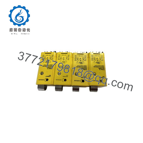
SDAS-01-7Y2S1024
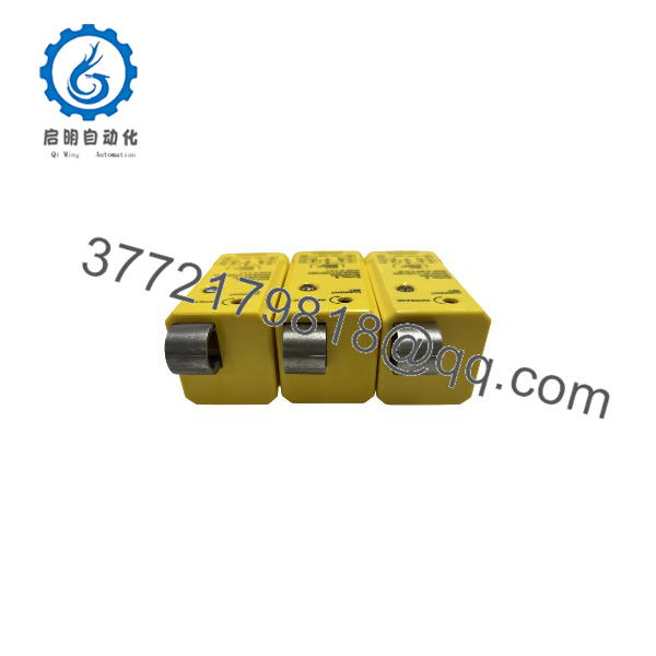
SDAS-01-7Y2S1024
System Compatibility & Integration Requirements
| Item / Dependency | Verified Compatibility or Requirement | Practical Note |
|---|---|---|
| Monitored line | AC power line, sensed current 1.5 to 15 A AC | Inductive coupling means no series element in the monitored line |
| Control supply | 24 VAC 50/60 Hz or 24 VDC, ±10% | 1.7 W / 1.7 VA consumption at 24 VAC |
| Mounting | Socket mount; manufacturer references KUP 3-pole sockets | Socket mounting allows replacement without rewiring |
| Output interface | 2 Form C (DPDT) contacts, 2 A @ 28 VDC / 1 A @ 120 VAC, resistive | Contact rating must be respected when driving inductive loads such as contactor coils |
| Trip setting | Onboard potentiometer, 1.5 to 15 A AC | Set point varies ±25% over the operating temperature range |
| Installation environment | −25 °C to +70 °C operating; plastic dust cover enclosure | Not an encapsulated or sealed housing |
Dimensions, Mounting & Connection Notes
| Item | Value |
|---|---|
| Mounting | Socket mount; two 0.156 in (3.96 mm) diameter mounting holes shown in the outline drawing |
| Outline | Maximum envelope 2.718 in (70.64 mm) per the manufacturer outline dimensions |
| Weight | Approx. 3.17 oz (90 g) |
| Enclosure | Plastic dust cover |
| Terminals | Connection is made through the socket; bottom-view wiring diagrams for the 1 Form C and 2 Form C versions are published in the manufacturer data |
FAQ
What is the Potter & Brumfield SDAS-01-7Y2S1024?
It is an adjustable undercurrent sensor relay from the SDAS-01 series, sensing 1.5 to 15 A AC on a monitored power line and switching an internal DPDT relay when the current falls below the potentiometer setting.
What is the difference between the SDAS-01-7 and SDAS-01-8 versions?
The 7-coded part numbers are undercurrent sensors that trip when current falls below the setting; the 8-coded part numbers are overcurrent sensors that trip when current exceeds the setting, with a 200 ms minimum time delay that allows starting and surge currents to pass.
How does the undercurrent trip work?
After control voltage is applied, a nominal 350 ms delay lets the line start drawing current; if the current then remains below the potentiometer setting for approximately 350 ms, the internal relay energizes and stays energized until the current again exceeds the setting or control voltage is removed.
What control voltage does the SDAS-01-7Y2S1024 require?
24 VAC at 50/60 Hz or 24 VDC, within ±10%, with a power requirement of 1.7 W or 1.7 VA at 24 VAC.
What contacts does it provide?
A 2 Form C (DPDT) internal relay rated 2 A at 28 VDC or 1 A at 120 VAC, resistive.
How is the sensor connected to the monitored line?
By inductive coupling to the power line, which introduces zero insertion loss — there is no series resistive element, voltage drop, or added heat in the monitored circuit.
How is the unit mounted?
It is socket mounted (the manufacturer references KUP 3-pole sockets), with a plastic dust cover enclosure and an approximate weight of 90 g.
What accuracy can be expected from the trip setting?
The set point varies by ±25% over the operating temperature range, so the application should tolerate that band around the chosen threshold.
Documented Performance Data
| Metric | Value | Condition |
|---|---|---|
| Trip delay (undercurrent) | 350 ms, typical | From the beginning of undercurrent after control voltage is applied; 200 ms minimum |
| Response window at turn-on | 350 ms, nominal | Power line current must begin within this window after control voltage is applied |
| Set point stability | ±25% | Over the full operating temperature range |
| Power consumption | 1.7 W / 1.7 VA | At 24 VAC control supply |