
 WhatsApp: +86 16626708626
 Email:
  Phone: +86 16626708626
Description
Key Technical Specifications
| Parameter | Specification Value |
| Manufacturer Model No. | GP2600-TC11 (2980070-01) |
| Display Type | TFT Color LCD |
| Display Size | 12.1 Inches (246.0 mm W × 184.5 mm H) |
| Resolution | 800 × 600 pixels (SVGA) |
| Display Colors | 256 Colors (No blink) / 64 Colors (Blink) |
| Input Voltage | 100 to 240 V AC (50/60 Hz) |
| Power Consumption | 50 VA or less |
| Application Memory | 4 MB FLASH EPROM |
| SRAM Backup Memory | 256 KB (Lithium Battery Backed) |
| Serial Interface (COM1) | RS-232C / RS-422 configurable (D-sub 25-pin female) |
| Serial Interface (COM2) | RS-232C (D-sub 9-pin male) |
| Ethernet Interface | 10BASE-T (RJ-45) |
| CF Card Interface | 1x CompactFlash Slot (Type II) |
| Enclosure Rating | IP65f / NEMA 4X / Type 13 (Front panel when mounted) |
| External Dimensions | 317 mm W × 243 mm H × 58 mm D |
| Cutout Dimensions | 301.5 mm W × 227.5 mm H |
Product Introduction & Supply Chain Strategy
The Pro-face GP2600-TC11 is a high-performance 12.1-inch SVGA color touchscreen panel engineered for plant automation, multi-driver PLC bridging, and networked process monitoring. Outfitted with dual serial ports, built-in 10BASE-T Ethernet, and a CompactFlash slot, it handles complex system graphic layouts on standard 100-240 V AC power.
Sourcing this unit as New Surplus offers superior long-term ROI and protects plant operations against unexpected EOL outages. Because Pro-face has officially discontinued the GP2000 series, purchasing genuine unused surplus stock eliminates the high risk of degraded backlights or worn resistive touch digitizers typical of used components. It serves as a direct, drop-in replacement that avoids thousands of dollars in cabinet redesigns or software migrations.
Installation & Configuration Guide
Stage 1: Pre-Installation (Prep & Safety)
- Execute Lock-Out/Tag-Out (LOTO) protocols on the main AC circuit feeding the cabinet panel.
- Put on an ESD-grounded wrist strap linked to cabinet earth ground before handling the unit.
- Take detailed photographs of all DIP switch positions, cable connections, ground leads, and wire labels on the old unit.
Stage 2: Removal
- Unplug the 100-240 V AC screw-terminal block and the protective earth ground wire from the rear chassis.
- Disconnect the Ethernet cable, CompactFlash card, and both serial communication connectors (COM1/COM2).
- Loosen the rear panel-mounting screw clamps holding the HMI frame against the enclosure cutout.
- Carefully extract the old panel forward through the cabinet cutout, making sure not to damage the cutout frame or gasket.
Stage 3: Installation (Clone & Seat)
- Inspect the front panel sealing gasket on the new GP2600-TC11 to ensure a tight IP65f/NEMA 4X seal.
- Match all physical DIP switch configurations from the original unit onto the replacement panel.
- Insert the new HMI into the existing 301.5 mm × 227.5 mm panel cutout from the front side.
- Attach and tighten the mounting clamps crosswise to uniform torque to prevent bezel distortion.
Stage 4: Power-On & Testing
- Check the line voltage with a multimeter to verify it falls strictly within the 100–240 V AC range.
- Reconnect the ground lead, AC power block, network connection, and serial communication cables.
- Power up the cabinet. Verify the power LED lights up solid green and the display boots into the system menu.
- Download the runtime project file (
.prw) via GP-PRO/PBIII or CF card, then test touchscreen calibration and PLC data communication.
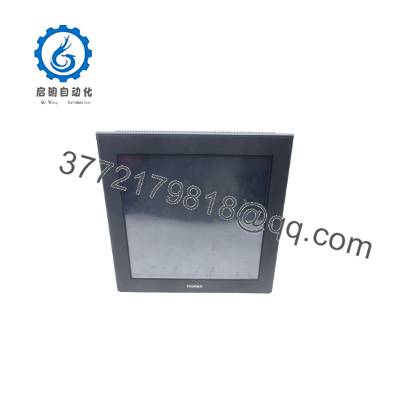
GP2600-TC11
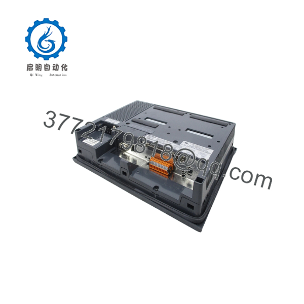
GP2600-TC11
Firmware/Software Versions & Upgrade Notes
- Programming Environment: The GP2600-TC11 is configured using GP-PRO/PBIII for Windows (Version 6.0 or higher recommended).
- System Program OS Matching: Verify that the system runtime program version flashed on the GP2600-TC11 matches the version used by your GP-PRO/PBIII compiler. Mismatched OS versions can cause driver faults or corrupted display pages.
- Dual Serial & Ethernet Protocols: COM1 supports RS-232C/RS-422 switching via software settings, while COM2 dedicated RS-232C allows simultaneous connection to barcode scanners or secondary PLCs alongside Ethernet data logging.
- Firmware Flash Protection: Do not disrupt AC power during a runtime project transfer or firmware OS update. Interrupting power during Flash EPROM writing will corrupt the internal memory chip and disable the bootloader.
Frequently Asked Questions (FAQ)
Why is New Surplus pricing higher than refurbished units, but lower than original OEM list prices?
New Surplus delivers maximum capital efficiency by eliminating operational risk. Refurbished parts are cheap because they reuse aged components prone to thermal breakdown and touchscreen wear. Our New Surplus inventory consists of genuine, unused original stock acquired from facility cancellations. You receive factory-grade reliability at a significantly reduced price compared to a complete system overhaul.
How can I be sure that this Pro-face GP2600-TC11 is unused and original?
Every in our inventory is certified Original New Surplus. Units have zero operational field hours, clean backplane pins, clear serial tags, and pristine glass surfaces. Packaging is opened exclusively under ESD-safe warehouse conditions for incoming quality control validation.
Since the GP2000 series is legacy, why should our facility maintain an on-site spare?
Keeping 1–2 units of the on-site serves as an essential risk mitigation strategy. If an operational HMI fails, having a pre-tested, direct replacement on the shelf converts days of unplanned downtime into a simple 30-minute swap, preserving production schedules and avoiding expensive emergency retrofits.
Can I hot-swap the while the control cabinet is powered on?
No. You must never disconnect or plug in an AC-powered HMI panel while the circuit is live. Disconnecting the 100-240 V AC power block or serial communications under load can cause electrical arcing, damage internal RS-232/422 transceivers, or blow protective fuses. Always isolate power before replacing hardware.
Will the HMI retain its screen files and recipe data during extended power loss?
Yes. Application logic and screen graphics reside in 4 MB non-volatile Flash EPROM, which preserves data without battery power. System variables, alarm logs, and SRAM recipe data are backed up by an internal lithium battery. Before placing long-stored surplus panels into service, verify the status of the internal SRAM battery.



