
 WhatsApp: +86 16626708626
 Email:
  Phone: +86 16626708626
Description
Key Technical Specifications
| Parameter | Value |
|---|---|
| Product Family | PS5000 Series Industrial PC |
| Platform Type | Modular panel computer |
| Global Code | PFXPP2LU7DA6L0NN00 |
| Modular Expansion | Two-slot PS5000 platform designation |
| Display Architecture | Separate modular display and computer sections |
| Display Options | 15 in, 15 in wide, 19 in wide, or 22 in wide, depending on configuration |
| CPU Options in PS5000 Family | Intel Atom, Intel Celeron, Intel Core i3, or Intel Core i7, depending on configuration |
| Memory Options in PS5000 Family | Approximately 1–16 GB, depending on platform and installed module |
| Storage Options | HDD, SSD, CFast card, or other configuration-specific media |
| Operating Systems | Windows 7, Windows 8.1 Industry, Windows 10 IoT Enterprise, or Windows Embedded variants, depending on configuration date |
| Video Connection | DisplayPort or configuration-specific display interface |
| Touch Connection | USB connection between host and display module |
| Ethernet | Available; exact port count and speed depend on installed computer module |
| Serial Ports | Configuration-dependent; verify the rear I/O label |
| Expansion Slots | Two PS5000 system slots indicated by the PP2 platform family |
| Rated Input | Typically DC 24 V for PS5000 panel configurations; verify the exact nameplate before energizing |
| Cooling | Fanless or managed thermal design, depending on the computer module |
| Mounting | Panel mounting or modular display mounting, depending on the complete assembly |
| Exact CPU | Must be read from the CPU module label or BIOS |
| Exact RAM | Must be verified from the installed memory module or system information |
| Exact Storage | Must be verified from the drive label or BIOS/operating system |
| Exact Display Size | Not confirmed from the indexed global code alone |
Pro-face uses global codes as universal model numbers, but the code contains configuration-specific hardware details that should be confirmed from the product label, configuration sheet, BIOS, and installed modules. The catalog lists multiple CPU, memory, storage, operating-system, display, and expansion combinations.
Product Introduction
The PRO-FACE PFXPP2LU7DA6L0NN00 is a Series modular industrial PC configuration for factory visualization, SCADA, data collection, machine control, and Windows-based automation applications. It uses a modular computer-and-display architecture with expansion capability for industrial interfaces.
Do not list this unit with guessed CPU, RAM, storage, operating system, or display size. The full global code identifies the configuration family, but the installed hardware must be verified from the nameplate and inspection. replacement planning generally points toward the PS6000 Series.
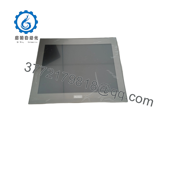
PFXPP2LU7DA6L0NN00
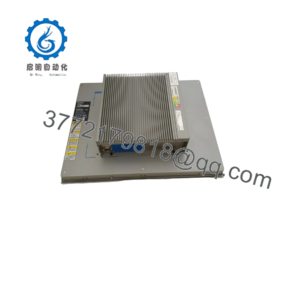
PFXPP2LU7DA6L0NN00
Troubleshooting Quick Reference
| Symptom | Possible Cause | Relevance to This Part | Quick Check Method | Recommendation |
|---|---|---|---|---|
| No power LED or no boot activity | Missing DC supply, reversed polarity, blown fuse, or failed power module | ✅ High | Read the exact voltage from the nameplate and measure directly at the power terminals during startup. Do not assume the supply type from the display model. | Correct the control power circuit first. Replace the computer only after confirming proper input voltage. |
| Display remains black but the PC appears to run | Display power, DisplayPort/video cable, backlight, or display module failure | ✅ High | Check the display’s power indicators, reseat the video and USB touch cables, and connect a known-good display if available. | Test the display separately from the computer module before replacing the complete panel PC. |
| BIOS appears but Windows does not load | Failed storage device, damaged operating-system image, or incorrect boot order | ✅ High | Enter BIOS, confirm the storage device is detected, and check the boot sequence. Review SMART data if the drive is accessible. | Clone or replace the storage device only after preserving the original application and recovery data. |
| No BIOS screen and no POST indication | RAM, CPU module, power, or motherboard fault | ✅ High | Disconnect nonessential USB and expansion devices. Check POST behavior, module seating, and diagnostic LEDs. | Reseat memory and expansion modules. Replace the failed computer module if POST remains absent. |
| Windows starts but the automation application does not | Missing runtime, license, driver, or corrupted application files | ✅ High | Boot into Windows, check Event Viewer and application startup logs, and verify the required runtime and license files. | Restore the approved image or application backup before replacing hardware. |
| Touch panel does not respond | USB touch cable, touch controller, driver, or display-panel fault | ✅ High | Check Windows Device Manager for the touch device and verify the USB connection between display and computer. | Replace the cable or touch controller first. A failed USB connection can look like a bad display. |
| Touch coordinates are inaccurate | Calibration data, driver mismatch, or touch-panel replacement | ✅ Medium | Run the Windows touch calibration utility and compare accuracy at all four corners. | Recalibrate after confirming the correct touch driver and display model. |
| Ethernet link is down | Damaged cable, disabled NIC, wrong driver, or failed Ethernet port | ✅ Medium | Check link LEDs, Device Manager, cable continuity, and switch-port status. Confirm the configured IP address. | Resolve the physical link and driver issue before replacing the motherboard. |
| PLC or field device communication is lost | Missing Windows driver, changed COM assignment, or application configuration loss | ✅ High | Compare Device Manager COM numbers and network settings with the original system image. Check the application’s device-driver configuration. | Restore the original image or configuration. Do not assume a hardware replacement preserves COM numbering. |
| System freezes under load | Storage degradation, RAM fault, thermal issue, or incompatible expansion card | ✅ High | Check Windows event logs, memory diagnostics, storage health, and CPU temperature. Remove expansion cards one at a time for isolation. | Verify thermal conditions and expansion-card compatibility before replacing the base unit. |
| System resets when an expansion card starts | Power-budget issue, shorted card, or defective slot | ✅ High | Remove the expansion card, confirm stable boot, and inspect the card and slot for contamination or bent contacts. | Calculate the slot power demand and test the card separately. |
| USB devices disconnect intermittently | Cable strain, grounding noise, damaged connector, or inadequate power | ✅ Medium | Test with a short known-good USB cable and monitor Windows USB event logs. Check shield and ground conditions near variable-speed drives. | Correct cable routing and grounding before replacing the USB controller. |
| Storage or project data disappears after power loss | Drive failure, corrupted filesystem, or inadequate shutdown | ✅ High | Check drive health, Windows event logs, and the system’s shutdown history. Confirm whether the application uses write-intensive logs. | Replace failing media with an approved industrial SSD and restore a verified image. |
| Replacement unit does not match the existing system | Different CPU, display, storage, OS, or expansion configuration | ✅ High | Photograph every module label and compare CPU, RAM, storage, display, power, and slot configuration before ordering. | Order by the complete PFX code plus module labels, not by the family name alone. |
If the fault remains unclear, provide technical support with photographs of every module label, BIOS information, Windows version, CPU and memory details, storage model, display size, measured input voltage, expansion cards, and application error logs.
Frequently Asked Questions (FAQ)
What type of product is PFXPP2LU7DA6L0NN00?
It is a configuration-specific global code for a Pro-face Series modular industrial PC. It is not a simple replacement display or standalone HMI. The system normally combines a computer module with a separate industrial display and touch interface.
Can the exact CPU, RAM, storage, and operating system be identified from this code?
Not reliably from the indexed public data alone. modular systems were available with several Intel CPU options, memory capacities, storage types, operating systems, display sizes, and expansion combinations. Read the computer module label, BIOS information, Windows System page, and storage label before publishing or ordering the unit.
Is this unit obsolete?
Yes. Pro-face identifies the Series as a discontinued product family. Core i7 and Celeron models reached end of sales on March 31, 2022, while Atom models reached end of sales on April 30, 2025. The applicable service date depends on the installed computer configuration.
What is the recommended replacement?
Pro-face identifies the PS6000 Series as the recommended substitution for the Series. It is not automatically a drop-in replacement. Verify display cutout, mounting method, operating system, storage image, expansion cards, fieldbus interfaces, software licensing, and application compatibility before scheduling a changeover.
Can I replace only the display module?
The modular architecture was designed to allow the display and computer sections to be serviced separately. However, the replacement display must match the video interface, touch interface, screen size, mounting arrangement, and cable set. Confirm the display’s model label and connector type before ordering a display-only replacement.
Does replacing the erase the PLC or SCADA application?
The PLC program normally remains in the PLC, but the Windows application, runtime, drivers, licenses, network settings, and screen configuration reside on the industrial PC’s storage. Create a sector-level storage image and export application licenses before removing the original unit. A replacement PC with the same part number may still contain different storage media or a blank operating-system image.
Why should the listing show the module labels and BIOS screen?
The global code alone does not prove the installed CPU, RAM, storage, operating system, display, or expansion hardware. For this model, a credible listing should include photographs of the complete code label, CPU module, memory, storage device, rear I/O, display label, BIOS summary, and power-up screen. Confirm whether the unit is New Original, New Surplus, or Refurbished, and state exactly what was tested.



