
 WhatsApp: +86 16626708626
 Email:
  Phone: +86 16626708626
Description
Key Technical Specifications
| Parameter | Value |
|---|---|
| Model | 5301-MBP-DFCM |
| Brand | ProSoft Technology |
| Product Family | ProLinx Gateway |
| Gateway Function | Modbus Plus to DF1 |
| Modbus Plus Port | 1 × configurable DB-9 port |
| DF1 Interface | Configurable serial communication |
| DF1 Mode | Master or Slave |
| Modbus Plus Mode | Master or Slave |
| Internal Database | Up to 4,000 registers |
| Configuration Software | ProSoft Configuration Builder |
| Supply Voltage | 24 VDC nominal |
| Allowed Supply Range | 18–36 VDC |
| Maximum Current | 500 mA |
| Operating Temperature | −20 to +50 °C |
| Storage Temperature | −40 to +85 °C |
| Relative Humidity | 5–95%, non-condensing |
| Mounting | DIN-Rail |
| Housing | Stand-alone protocol gateway |
The ProLinx architecture uses an internal database as the data exchange area between protocol drivers. Configuration, application data, and status information are maintained in separate database areas.
Product Introduction
The ProSoft Technology 5301-MBP-DFCM is a ProLinx protocol gateway that connects Modbus Plus networks with DF1 Master/Slave devices. It is designed for legacy control systems where Modbus Plus equipment must exchange data with Allen-Bradley and other DF1-based devices.
The gateway provides configurable protocol drivers and an internal data table for moving information between the two networks. ProSoft documentation also describes support for user-defined Modbus Plus commands, making the module suitable for existing control architectures that cannot be easily migrated.
Installation & Configuration Guide
Stage 1: Pre-Installation Preparation — 5 Minutes
⚠️ Safety First: Place the controlled process in a safe state and follow the site’s lockout/tagout procedure before removing the existing gateway.
Tools Required:
- ESD wrist strap
- Small screwdriver
- Digital multimeter
- Wire labels
- Smartphone or camera
Data Backup:
- Record the existing 5301-MBP-DFCM configuration.
- Save the configuration file from ProSoft Configuration Builder if available.
- Photograph the Modbus Plus connection and serial wiring.
- Record DF1 station address and communication parameters.
- Document the Modbus Plus node/network configuration.
- Record any application command lists.
Stage 2: Removing the Old Module — 5 Minutes
- Remove power from the gateway.
- Label each connected cable.
- Disconnect the Modbus Plus cable carefully.
- Disconnect the DF1 serial wiring.
- Release the DIN-rail mounting mechanism.
- Remove the module straight from the mounting rail.
- Inspect the wiring and mounting location before installation.
⚠️ Keep the old gateway available until the replacement has passed communication testing.
Stage 3: Installing the New Module — 5–10 Minutes
- Verify the exact model: 5301-MBP-DFCM.
- Wear an ESD wrist strap before handling the module.
- Secure the gateway on the DIN rail.
- Reconnect the Modbus Plus network connection.
- Reconnect the DF1 serial interface.
- Confirm that the power wiring is correctly identified.
- Clone the original communication settings before attempting live data exchange.
The 5301-MBP-DFCM uses a configurable Modbus Plus port, while DF1 ports can be configured for Master or Slave operation.
Self-Checklist:
- Exact model verified
- DIN-rail mounting secured
- Modbus Plus wiring verified
- DF1 wiring verified
- Node/address settings recorded
- DF1 baud and framing settings verified
- Configuration file available
Stage 4: Power-On & Testing — 10 Minutes
- Measure the DC supply before applying power.
- Confirm the supply is within the specified operating range.
- Apply power to the gateway.
- Observe the module and communication status LEDs.
- Connect the engineering computer and open the configuration software.
- Verify the loaded configuration.
- Check Modbus Plus communication with the intended nodes.
- Check DF1 communication with the connected device.
- Verify that data is appearing in the internal database.
- Perform controlled read/write testing before returning the process to automatic operation.
⚠️ Configuration Trap: Do not copy only the physical wiring. The DF1 station address, baud rate, parity, protocol mode, and Modbus Plus network parameters must also match the existing application.
The ProLinx internal database acts as the exchange area between the communication drivers, and command configuration determines how data is transferred between external devices and the database.
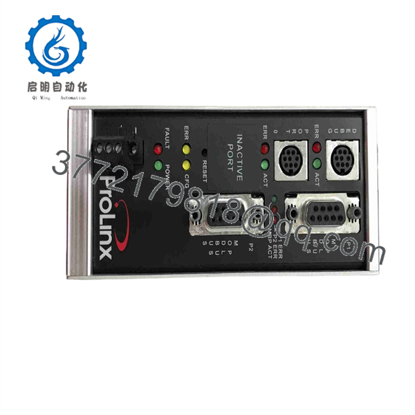
5301-MBP-DFCM
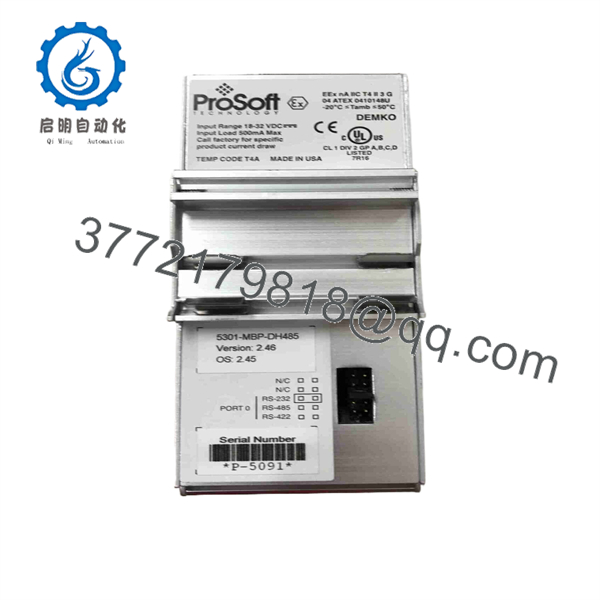
5301-MBP-DFCM
Frequently Asked Questions (FAQ)
Can the 5301-MBP-DFCM connect Modbus Plus equipment to Allen-Bradley PLCs?
Yes. The gateway was designed to connect Modbus Plus networks with DF1 devices, including applications involving Rockwell Automation PLC platforms using DF1 communications.
Is the DF1 interface Master or Slave?
It can be configured for DF1 Master or DF1 Slave operation. The exact configuration depends on the architecture and which device is controlling the communication transaction.
Can the Modbus Plus port operate as a Master or Slave?
Yes. The Modbus Plus driver supports both Master and Slave functionality. Master operation uses configured commands to exchange information with devices on the Modbus Plus network.
How much internal data can the gateway store?
The ProLinx documentation describes an internal database with registers used for application data, status information, and configuration. The Modbus Plus documentation uses an address range extending through register 3,999 for command data, corresponding to a 4,000-register internal data area.
What power supply does the 5301-MBP-DFCM require?
The commonly documented specification is 24 VDC nominal, with an allowable input range of approximately 18–36 VDC. Maximum current is listed at approximately 500 mA. Verify the nameplate and applicable hardware documentation for the exact revision before energizing a replacement.
Is this a modern replacement for a current network gateway?
No direct modern-equivalent assumption should be made. The 5301-MBP-DFCM belongs to the older ProLinx 5000-series gateway family, and Modbus Plus/DF1 are legacy protocols. If replacing it with newer hardware, verify protocol behavior, addressing, data mapping, serial framing, command handling, and PLC compatibility rather than treating the substitution as a pin-for-pin replacement.



