
 WhatsApp: +86 16626708626
 Email:
  Phone: +86 16626708626
Description
Key Technical Specifications
| Parameter | Specification Value |
| Catalog Number | MVI56-PDPMV1 |
| Backplane Compatibility | Allen-Bradley ControlLogix (1756 Local or Remote Chassis) |
| Backplane Current Load | 800 mA @ 5.1 V DC; 3 mA @ 24 V DC |
| Communication Port | 1 x DB-9 Female (PROFIBUS DP Port) |
| Protocol Supported | PROFIBUS DP-V1 Master (Class 1 & Class 2), PROFIBUS DP-V0 |
| Baud Rate Support | 9.6 kbps to 12 Mbps (Auto-baud detection support) |
| Maximum Slave Count | Supports up to 125 PROFIBUS DP Slaves |
| Data Capacity | Up to 1536 bytes input data, 1536 bytes output data |
| Acyclic Comms (DPV1) | Class 1 & Class 2 acyclic messaging for HART & smart drives |
| Isolation Voltage | 500 V optical isolation from backplane |
| Configuration Port | 1 x RJ45 RS-232 Configuration / Diagnostic Port |
| Operating Temperature | 0°C to 60°C (32°F to 140°F) |
Product Introduction
The ProSoft MVI56-PDPMV1 is a single-slot ControlLogix in-chassis communication module that bridges Allen-Bradley PACs directly onto PROFIBUS DP networks. Operating as a full PROFIBUS DP-V1 Master (Class 1 and Class 2), it allows your ControlLogix system to exchange high-speed cyclic I/O data with variable frequency drives, motor management systems, instrumentation, and remote I/O blocks without requiring external protocol converters or standalone gateways.
It features complete acyclic messaging capabilities, enabling real-time configuration, calibration, and diagnostics for field devices via HART pass-through or PROFIBUS DP-V1 messaging blocks. Equipped with automatic baud rate detection up to 12 Mbps and custom Add-On Instructions (AOI) for RSLogix 5000 / Studio 5000, the MVI56-PDPMV1 provides native tag integration into ControlLogix memory structures for seamless commission and commissioning turnaround times.
Troubleshooting Quick Reference
| Symptom | Possible Cause | Relevance to this Part | Quick Check Method | Recommendation |
| Module OK LED Off / Unlit | Missing backplane power or rack fault | ❌ Low | Measure 5.1V DC backplane voltage using a multimeter on the rack power supply test points. | Check 1756-PA72/PB72 power supply output before replacing module hardware. |
| ERR / SYS LED Red | PROFIBUS Master configuration failure or GSD mismatch | ✅ High | Check diagnostic data array in RSLogix/Studio 5000 for configuration error codes. | Verify master configuration using ProSoft Configuration Builder (PCB) and reload GSD files. |
| PB COM LED Red / Flashing | Bus cable short, missing termination, or slave offline | ❓ Medium | Check DB-9 connector switch termination position at both ends; test line continuity. | Ensure 220Ω termination switches are set to “ON” at physical end-nodes only. |
| ControlLogix I/O LED Yellow | Module backplane block transfer mismatch | ✅ High | Verify ladder logic matches the required MVI56-PDPMV1 block transfer tags. | Re-import the exact MVI56-PDPMV1 Sample Add-On Instruction (AOI) file. |
| Slave Device Missing (Token Loss) | Baud rate too high for segment cable length | ❌ Low | Verify total segment distance against baud rate limits (e.g., 100m max at 12 Mbps). | Lower network baud rate in master setup or add a PROFIBUS repeater. |
Note: If you run into recurring communication dropouts, capture your ProSoft Configuration Builder (PCB) live bus monitor logs and submit them to our technical support team.
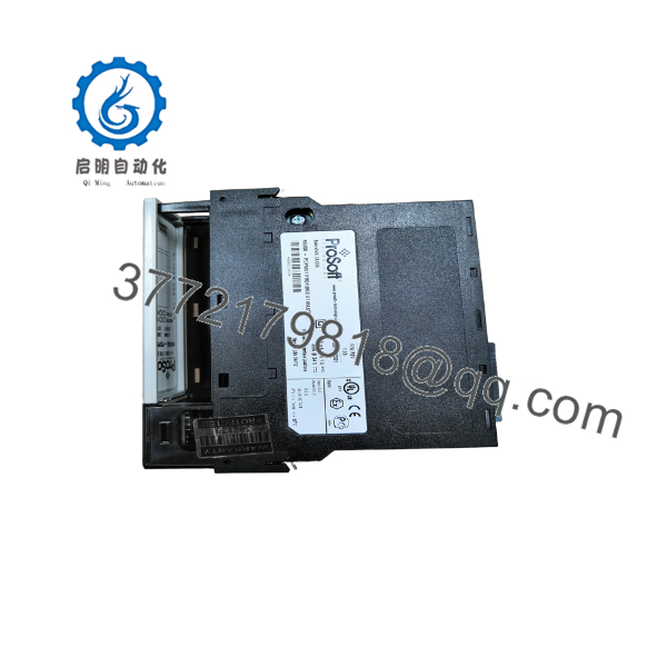
MVI56-PDPMV1
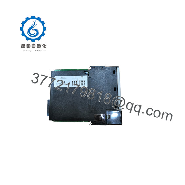
MVI56-PDPMV1
Frequently Asked Questions (FAQ)
Q: What is the benefit of DP-V1 support compared to standard PROFIBUS DP-V0?
A: PROFIBUS DP-V0 only supports deterministic cyclic data exchange (I/O signals). DP-V1 adds acyclic parameter read/write commands on top of cyclic traffic. This lets you read drive fault codes, reconfigure HART transmitters on the fly, and modify parameter blocks directly from your ControlLogix ladder logic without interrupting high-speed cyclic control loop polling.
Q: Can I configure this module directly within Studio 5000?
A: You define the backplane I/O footprint and sample logic in Studio 5000 using ProSoft-provided Add-On Instructions (AOI). However, building the actual PROFIBUS network topology (adding slave nodes, assigning bus addresses, importing GSD files) is completed using the free ProSoft Configuration Builder (PCB) software connected via the front RJ45 serial configuration port.
Q: Is the DB-9 PROFIBUS port isolated from the ControlLogix backplane?
A: Yes. The DB-9 communication interface features 500V optical isolation to shield the backplane bus from field ground loops, electrostatic spikes, and noise generated by high-power variable frequency drives on the PROFIBUS network.
Q: Does this module require an external 24V DC power supply?
A: No. The MVI56-PDPMV1 draws all required operating power directly from the 1756 ControlLogix backplane (800 mA at 5.1V DC). No auxiliary external power wiring is needed on the front panel.
Q: How do I know whether I am receiving a New Surplus or Refurbished module?
A: We state the exact condition clearly on every listing. “New Surplus” units are unused items in original factory packaging or open-box plant spares. “Refurbished” units undergo complete cleaning, component inspection, electrolytic capacitor checks, and 24-hour functional load testing on a live 1756 rack. Every unit ships with an official serial-numbered QA Test Certificate.
SOP Quality Control Process
1. Inbound Inspection & Traceability
- Authentic OEM serial tag and barcode verification against factory records.
- Inspection of DB-9 port pins, backplane card edge connectors, and shell housing.
- Visual check for thermal degradation, PCB hairline cracks, solder rework, or internal corrosion.
2. Live Bench & Functional Testing
- Inserted into a live 1756-A10 chassis powered by a genuine 1756-PA72 power supply.
- Established configuration handshake using ProSoft Configuration Builder (PCB) via serial connection.
- Built a multi-node test network with remote PROFIBUS DP slaves (ET 200S rack and VFD interface card); run 24-hour continuous cyclic and acyclic DP-V1 data transfer test at 12 Mbps.
- Front panel status LED indicators verified across all operational states.
3. Electrical Parameter & Safety Checks
- 500V DC optical isolation verified between DB-9 communication port and backplane ground lines.
- Ground continuity tested with a Fluke 115 multimeter from the chassis frame clip to ground planes.
4. Firmware & Configuration Verification
- Existing firmware revision recorded. Upgraded to the latest stable ProSoft release where applicable.
- Memory bank and register read/write integrity fully confirmed.
5. Final QC & Packaging
- Sealed inside a static-shielding ESD bag with fresh desiccant.
- Boxed using heavy-duty corrugated shipping materials with custom foam cushioning.
- Signed QA Pass certificate generated and attached with full serial number tracking.
Technical Pitfall & Survival Guide
- ❗ GSD File Revision Mismatch: When adding field devices, always match the device GSD file version to the exact hardware revision on the shop floor. Using an updated or incorrect GSD file will prevent the master from establishing cyclic data exchange with the slave, triggering a permanent bus error.
- ❗ Improper Line Termination: PROFIBUS DP requires active termination switches set to “ON” at the two physical end-nodes of the cable run, and “OFF” at all intermediate nodes. Leaving an intermediate switch ON or forgetting end-node termination creates line impedance mismatches and reflections that crash communication above 1.5 Mbps.
- ❗ Shield Grounding Errors: PROFIBUS cable shielding must be connected to earth ground at every device using heavy-duty cable clamps. In noisy industrial environments, relying solely on the DB-9 connector shell for grounding risks noise coupling into signal lines, causing high frame drop rates.
- ❗ ESD Hazard: PROFIBUS communication cards contain sensitive transceivers and CMOS logic components. Always wear a grounded ESD wrist strap when handling the unit. Touching the backplane gold fingers without ESD mitigation can damage internal bus driver chips before installation is completed.



