WhatsApp: +86 16626708626
 Email:
 Phone: +86 16626708626
Description
Key Technical Specifications
| Parameter | Specification |
|---|---|
| Manufacturer | ProSoft Technology |
| Model | MVI56E-MCMR |
| Product category | Enhanced Modbus Master/Slave Communications Interface |
| Host platform | Rockwell Automation ControlLogix |
| Chassis interface | Single-slot 1756 ControlLogix backplane |
| Modbus modes | RTU and ASCII |
| Serial ports | 2, independently configurable |
| Serial standards | RS-232, RS-422, RS-485 |
| Baud rate | 110 baud to 115.2 kbps |
| Data bits | 5, 6, 7, or 8, subject to protocol configuration |
| Stop bits | 1 or 2 |
| Parity | None, odd, or even |
| User memory database | 5,000 16-bit registers |
| Scheduled data block | 40 words |
| Configuration Ethernet port | 10/100Base-T, RJ45 |
| Configuration software | ProSoft Configuration Builder |
| Backplane current at 5 VDC | 800 mA |
| Backplane current at 24 VDC | 3 mA |
| Operating temperature | 0°C to 60°C (32°F to 140°F) |
| Storage temperature | −40°C to 85°C (−40°F to 185°F) |
| Relative humidity | 5% to 95%, noncondensing |
| Operational shock | 30 g |
| Nonoperational shock | 50 g |
| Vibration | 5 g from 10 to 150 Hz |
| Serial-port isolation | 500 V optical isolation from the backplane |
| Status indicators | APP and OK LEDs; four-character scrolling alphanumeric display |
Source: ProSoft Technology’s official MVI56E-MCMR datasheet and user manual.
Product Introduction
The ProSoft Technology MVI56E-MCMR is an enhanced Modbus serial communication module for the Rockwell Automation ControlLogix platform. It connects ControlLogix processors to Modbus RTU and ASCII devices through two independently configurable serial ports, each supporting RS-232, RS-422, or RS-485. Its reduced scheduled data block is designed for applications where ControlLogix data exchange occurs over constrained networks, including remote rack architectures using ControlNet.
The module maintains a 5,000-register user database and supports configurable Modbus master and slave operation. An onboard Ethernet port provides configuration and diagnostics access, while a removable nonvolatile CompactFlash personality module can retain configuration settings for field replacement.
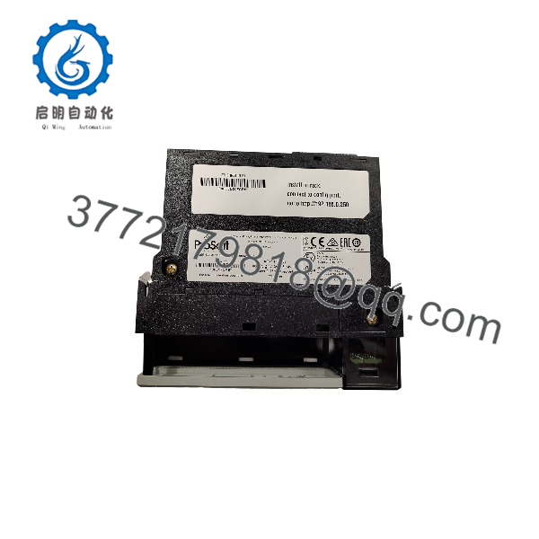
MV156E-MCMR
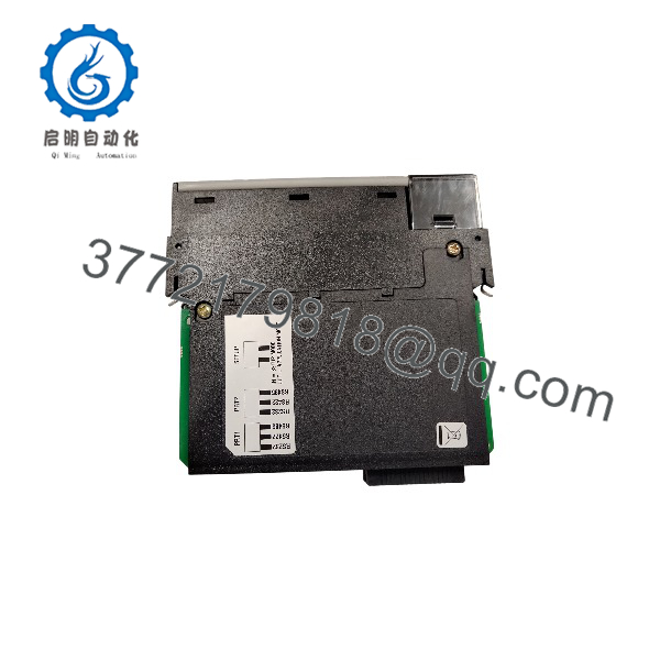
MV156E-MCMR
Installation & Configuration Guide
Stage 1: Pre-Installation Preparation
Estimated time: 10–20 minutes
- Confirm the exact model. Check the module label for
MVI56E-MCMR. Do not order or install based solely on the potentially mistypedMV156E-MCMR. - Verify chassis compatibility. Confirm the existing controller, 1756 chassis, available slot, and module configuration against the ProSoft manual.
- Back up the application. Save the ControlLogix project, relevant ladder logic or Add-On Instructions (AOIs), module configuration, Modbus register mapping, and master command lists.
- Record serial settings. Document each port’s role, baud rate, parity, stop bits, electrical interface, slave addresses, and communication timing.
- Check replacement configuration. If the original module has a personality module, confirm that it is compatible with the replacement hardware and contains the expected configuration.
- Prepare tools and documentation. Have the applicable ProSoft user manual, ControlLogix project, configuration software, and approved ESD equipment available.
Safety warning: Follow the site’s lockout/tagout procedure and the chassis manufacturer’s instructions before removing or inserting the module. Do not assume that this module supports hot swapping.
Stage 2: Remove the Existing Module
Estimated time: 5–10 minutes
- Notify operations and place the affected Modbus communications and control functions in the approved maintenance state.
- Confirm the required isolation procedure for the ControlLogix chassis.
- Label both serial-port connections and the configuration Ethernet connection.
- Disconnect the serial cables without pulling on their conductors.
- Release the module’s retaining mechanism and withdraw it according to the chassis instructions.
- Inspect the module connector, chassis slot, and serial connectors for damage.
- Retain the original module and its configuration media until the replacement has passed acceptance testing.
Stage 3: Install the Replacement
Estimated time: 5–15 minutes
- Verify the replacement part number and inspect its condition.
- Confirm that the replacement’s hardware and firmware are suitable for the existing application.
- Check whether the configuration is stored on a compatible personality module or must be restored from a backup.
- Install the module in the approved ControlLogix slot, following the chassis installation procedure.
- Reconnect the serial cables to the correct ports and restore the original RS-232, RS-422, or RS-485 wiring arrangement.
- Verify serial interface jumpers, where applicable, before powering the system.
- Confirm that the module is properly seated and secured.
Pre-commissioning checklist
Stage 4: Power-On and Commissioning
Estimated time: 15–30 minutes for basic verification; longer for complex networks
- Restore power according to the approved maintenance procedure.
- Observe the module’s status LEDs and four-character scrolling display.
- Connect to the module through its configuration Ethernet port and use the supported ProSoft configuration software.
- Verify the firmware version, serial-port settings, and module configuration.
- Restore the saved configuration if required, then confirm that the ControlLogix project contains the correct module data-transfer logic.
- Check each serial port independently. Confirm that the configured master can poll its slave devices or that the configured slave responds to its master.
- Verify register mapping, data types, word order, and error/status counters.
- Confirm that the ControlLogix processor receives valid data and that downstream logic behaves as expected.
- Document the final configuration and obtain operations approval before returning the system to service.
Common troubleshooting checks
- No Modbus response: Verify the selected electrical interface, wiring polarity, baud rate, parity, stop bits, node address, and termination where applicable.
- Communication works but values are incorrect: Check register offsets, function codes, data types, floating-point representation, and word order.
- Module reports configuration errors: Compare the active configuration with the backup and confirm compatibility with the installed firmware.
- PLC data does not update: Check the ControlLogix module definition, scheduled data block, ladder logic or AOI, and module status data.
Important: A working serial link does not prove that the application data is correct. Validate actual register values against the field device and the ControlLogix program before handing the system back to operations.
Frequently Asked Questions
Q1. What does the ProSoft MVI56E-MCMR do?
It provides Modbus RTU and ASCII serial communications for ControlLogix processors. The module can operate as a Modbus master or slave and supports two independently configurable serial ports.
Q2. What is the difference between MVI56E-MCMR and MVI56E-MCM?
Both modules support enhanced Modbus master/slave communications on the ControlLogix platform. The MVI56E-MCMR uses a reduced scheduled data block, which is useful in remote rack applications where network bandwidth is constrained. ProSoft recommends the MVI56E-MCM for EtherNet/IP applications where bandwidth is not an issue. Confirm the data-transfer architecture before selecting a replacement.
Q3. Can the MVI56E-MCMR communicate over RS-485?
Yes. Each of its two serial ports can be configured for RS-232, RS-422, or RS-485. The electrical interface and communication parameters must match the connected Modbus equipment.
Q4. Does the module support both Modbus master and slave modes?
Yes. Each serial port can be configured independently as a master or slave. This permits different roles on separate serial networks, subject to the application’s configuration and available resources.
Q5. Will replacing the module preserve the original configuration?
The module supports a removable, nonvolatile CompactFlash personality module for storing configuration settings. However, do not assume that every replacement will automatically inherit the original configuration or that the saved configuration is compatible with every hardware or firmware revision. Back up the configuration and verify it during commissioning.
Q6. Is the MVI56E-MCMR compatible with every ControlLogix controller?
No. Compatibility depends on the ControlLogix platform, chassis, controller project, module firmware, and supported configuration. Verify the specific controller and software versions against the ProSoft documentation before installation.
Q7. How should I verify condition and availability before purchasing?
Request confirmation of the exact part number, hardware and firmware revisions, physical condition, included configuration media, test status, warranty, and dispatch lead time. For a critical production line, ask whether the supplier can provide a functional test report and whether the unit has been tested with the appropriate ControlLogix and serial communication setup.