
 WhatsApp: +86 16626708626
 Email:
 Phone: +86 16626708626
Description
Key Technical Specifications
| Parameter | Specification |
|---|---|
| Manufacturer | ProSoft Technology |
| Model | MVI69-MCM |
| Module type | Modbus Master/Slave Network Interface Module |
| Host platform | CompactLogix; supported MicroLogix 1500 LRP controllers |
| Backplane compatibility | Single-slot 1769 module |
| Application ports | 2 serial ports, P1 and P2 |
| Electrical interface | RS-232, RS-422, or RS-485, jumper-selectable |
| Protocols | Modbus RTU and Modbus ASCII |
| Port configuration | Each port independently configured as master or slave |
| Master command capacity | Up to 100 commands per port |
| Supported baud rates | 110 to 115,200 baud |
| Data bits | 7 or 8 |
| Stop bits | 1 or 2 |
| Parity | None, even, or odd |
| RTU error checking | CRC-16 |
| ASCII error checking | LRC |
| Floating-point data | Supports configurable Enron, Daniel, and other formats |
| Modbus functions | Includes read/write coils and registers, diagnostics, and slave identification functions, subject to master/slave mode |
| Configuration software | ProSoft Configuration Builder |
| Configuration method | Configuration text file downloaded to the module |
| Processor data transfer | Ladder logic; sample ladder file provided |
| Configuration port | RS-232, RJ45 connector with supplied cable |
| Application-port isolation | 500 V optical isolation from the backplane |
| Maximum backplane current | 800 mA at 5 VDC |
| Operating temperature | 0°C to 60°C (32°F to 140°F) |
| Storage temperature | −40°C to 85°C (−40°F to 185°F) |
| Relative humidity | 5–95%, non-condensing |
| Status indicators | Module status, application status, serial-port activity, configuration-port activity |
Specifications are based on ProSoft Technology’s published datasheet and user manual. The supported controller list has exceptions, so confirm the exact CompactLogix or MicroLogix catalog number before ordering.
Product Introduction
The ProSoft MVI69-MCM is a serial communication module that connects compatible CompactLogix and MicroLogix 1500 LRP controllers to Modbus-based field equipment. It supports Modbus RTU and Modbus ASCII over two independently configurable serial ports. Each port can operate as a master or slave, allowing the PLC to poll external instruments or make controller data available to another Modbus master.
The module is intended for industrial systems that need serial interoperability with instruments, drives, meters, and third-party controllers. Its configurable port settings and support for multiple floating-point data formats help accommodate different device requirements. The MVI69-MCM is a legacy product, so replacement planning should account for its 1769 backplane compatibility, controller model, existing ladder logic, port wiring, and configuration file. ProSoft identifies the MVI69E-MBS as a replacement option, but migration compatibility must be verified before deployment.
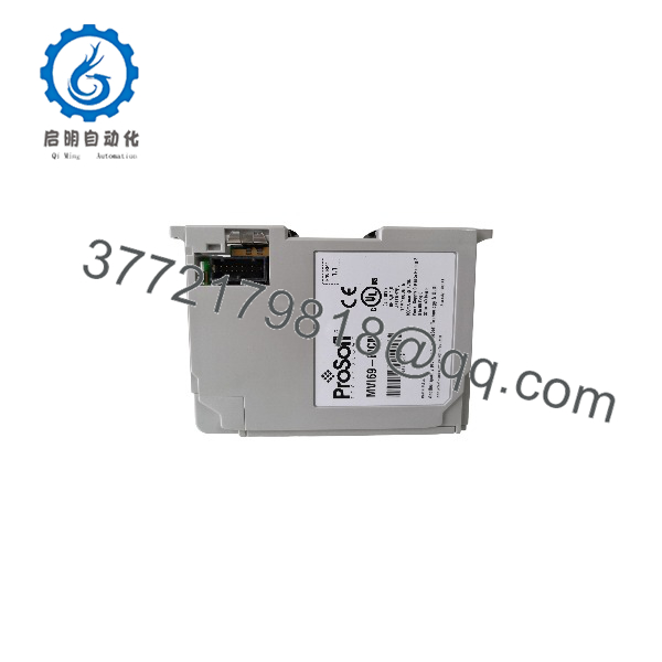
MVI69-MCM
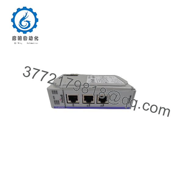
MVI69-MCM
Installation & Configuration Guide
Estimated durations are planning estimates, not manufacturer-prescribed installation times.
Stage 1 — Verify compatibility and back up the project
Estimated time: 15–30 minutes
- Confirm that the module label reads MVI69-MCM.
- Verify the controller model and the 1769 bus configuration.
- Check the module’s position and power-supply distance requirements.
- Back up the controller project, ladder logic, and ProSoft configuration text file.
- Record the current Modbus addresses, serial settings, register mapping, and port roles.
Stage 2 — Install the module and wire the serial ports
Estimated time: 15–30 minutes
- Place the system in a safe state and follow site lockout/tagout procedures.
- Install the module according to the applicable 1769 hardware instructions.
- Set the hardware jumpers for RS-232, RS-422, or RS-485 as required.
- Connect each application port using the correct cable and terminal arrangement.
- Check RS-485 polarity, grounding, shielding, and termination where applicable.
Stage 3 — Configure Modbus and processor data transfer
Estimated time: 30–90 minutes
- Open ProSoft Configuration Builder and load or create the module configuration.
- Configure each port’s protocol, master/slave role, baud rate, parity, data bits, and stop bits.
- Define master command lists or slave addressing and data behavior as required.
- Set floating-point format and register mapping to match the connected device.
- Integrate the sample or existing ladder logic into the controller project to transfer data between the processor and module.
Stage 4 — Commission and validate communication
Estimated time: 30–60 minutes
- Check the module and application status indicators.
- Verify serial transmit/receive activity on each configured port.
- Test representative Modbus reads and writes using approved test values.
- Confirm that the returned data appears in the intended controller tags and that register offsets and word order are correct.
- Check for timeout, framing, parity, and configuration errors.
- Save the verified configuration and update the system documentation.
Commissioning caution: A successful serial connection does not guarantee correct process data. Verify the device’s register map, addressing convention, and floating-point format before enabling writes to operating equipment.
Frequently Asked Questions
Q1: What is the ProSoft MVI69-MCM used for?
It provides Modbus serial communication between supported CompactLogix or MicroLogix 1500 LRP controllers and external Modbus devices.
Q2: Does the MVI69-MCM support both Modbus RTU and Modbus ASCII?
Yes. It supports RTU mode with CRC-16 error checking and ASCII mode with LRC error checking. The selected mode must match the connected device.
Q3: How many serial ports does the module have?
It has two application ports, P1 and P2. Each port can be configured independently for master or slave operation and can use RS-232, RS-422, or RS-485, depending on its hardware jumper settings.
Q4: How many Modbus commands can each master port execute?
The published specifications support up to 100 commands per port when configured as a Modbus master. The actual polling performance depends on the command list, serial settings, response times, and connected devices.
Q5: Is the MVI69-MCM compatible with all CompactLogix controllers?
No. Compatibility depends on the controller and platform configuration. ProSoft’s documentation lists supported CompactLogix and MicroLogix 1500 LRP controllers with exceptions. Check the current compatibility documentation for the exact controller catalog number before installation.
Q6: What software is needed to configure the module?
ProSoft Configuration Builder is used to prepare and manage the module configuration. Ladder logic transfers data between the module and the controller. ProSoft provides sample ladder logic and a user manual for integration and diagnostics.
Q7: What is the recommended replacement for the MVI69-MCM?
ProSoft lists the MVI69E-MBS as a replacement option. It is an enhanced Modbus serial module, but the replacement process may require changes to the controller project, configuration, and hardware setup. Confirm the migration instructions and compatibility before ordering.



