
 WhatsApp: +86 16626708626
 Email:
  Phone: +86 16626708626
Description
Key Technical Specifications
| Parameter | Value |
|---|---|
| Manufacturer | Proteus Industries |
| Model | 98008RFRSA10P1 |
| Product Type | Flow Meter Switch Controller |
| Primary Function | Flow monitoring / switch control |
| Manufacturer Part Number | 98008RFRSA10P1 |
| Application | Industrial fluid-flow monitoring and control |
| Communication Protocol | Not verified from available documentation |
| Supply Voltage | Not verified |
| Output Type | Not verified |
| Flow Range | Not verified |
| Operating Temperature | Not verified |
| Dimensions | Not verified |
Technical verification note: Publicly indexed sources confirm the manufacturer, exact model number, and controller classification, but they do not provide enough reliable documentation to establish voltage, flow range, output configuration, dimensions, or communications specifications. Those values should not be guessed when selecting a replacement.
Product Introduction
The Proteus Industries 98008RFRSA10P1 is identified as a Flow Meter Switch Controller used for industrial flow-monitoring and control applications. The exact model number is important because available listings associate it specifically with Proteus Industries rather than with a generic PLC I/O platform.
For replacement work, verify the nameplate, electrical connections, sensing arrangement, and controller configuration before installation. Public inventory listings currently show this exact part number in the secondary market, including used units, so condition should be confirmed before purchase.
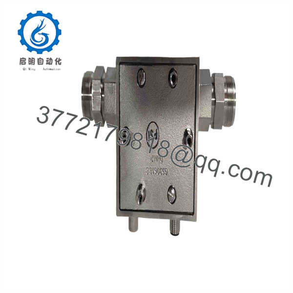
98008RFRSA10P1
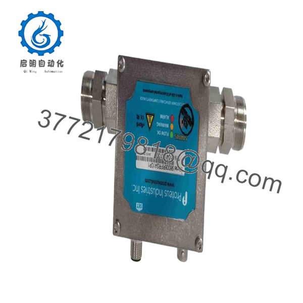
98008RFRSA10P1
Installation & Configuration Guide
Stage 1: Pre-Installation Preparation — Allow 10–15 minutes
- ⚠️ Place the equipment in a safe operating state. Notify operations before interrupting the flow-control circuit.
- Apply lockout/tagout to the relevant electrical supply and isolate the associated fluid system where required.
- Allow connected electrical components to discharge according to the equipment manufacturer’s procedure.
- Prepare an ESD wrist strap, multimeter, wire labels, screwdriver set, and phone/camera.
- Photograph the existing 98008RFRSA10P1 from several angles before removal.
- Record every wire position and identify the associated flow sensor, switch circuit, and controller terminals.
- Record the complete nameplate information, including 98008RFRSA10P1, revision information, and any configuration markings.
Stage 2: Removing the Existing Controller — Allow 5–10 minutes
- Verify that power is isolated with a properly rated multimeter.
- Mark each conductor before disconnecting it.
- Photograph the terminal arrangement again immediately before removing the wires.
- Disconnect the wiring without pulling on the conductors.
- Remove the mounting hardware or release mechanism used by the installed unit.
- Remove the controller carefully and inspect the mounting area and wiring for corrosion, damaged insulation, loose terminals, or contamination.
- ⚠️ Keep the original unit available for comparison. Do not discard it until the replacement has completed commissioning.
Stage 3: Installing the Replacement — Allow 5–10 minutes
- Confirm that the replacement nameplate reads exactly 98008RFRSA10P1.
- Compare the physical connector and terminal arrangement against the removed unit.
- Do not assume that similarly numbered flow controllers have identical electrical interfaces.
- Transfer wiring according to the original installation drawing or verified terminal documentation.
- Check conductor retention and terminal tightness.
- Verify that the sensing element and associated tubing/piping connections have not been disturbed.
- Confirm that the controller is mechanically secure before energizing.
Self-check:
- Exact model number verified
- Wiring photographed and labeled
- Terminal positions verified
- Mounting secure
- Sensor connections checked
- Supply voltage independently verified
Stage 4: Power-On & Functional Testing — Allow 10–15 minutes
- Measure the supply voltage before connecting the controller. Do not apply an assumed voltage.
- Energize the controller according to the equipment’s approved startup procedure.
- Check for abnormal LED indications, noise, overheating, or unexpected switching.
- Restore the associated flow circuit gradually.
- Confirm that the controller responds correctly to the actual flow condition.
- Verify the downstream PLC/DCS input or control circuit, if one is connected.
- Test the switching function at the required operating condition.
- Record the final operating state and any configured setpoints.
⚠️ Important: The available public documentation does not establish the 98008RFRSA10P1’s exact supply voltage, terminal assignments, setpoint range, or output specification. Do not commission the unit from a generic wiring assumption. Obtain the applicable Proteus documentation or compare the original unit’s nameplate and wiring diagram first.
Frequently Asked Questions
Q1. What is the Proteus 98008RFRSA10P1?
It is identified in current product listings as a Proteus Industries Flow Meter Switch Controller, with 98008RFRSA10P1 as the manufacturer part number.
Q2. Is 98008RFRSA10P1 a PLC CPU or standard PLC I/O module?
No reliable source found for this exact part number identifies it as a conventional PLC CPU or general-purpose I/O card. The available listing specifically classifies it as a Flow Meter Switch Controller.
Q3. What supply voltage does the 98008RFRSA10P1 require?
The exact supply voltage could not be verified from the reliable indexed sources located for this model. Do not apply 24 V DC or another assumed voltage without checking the unit’s nameplate or OEM documentation.
Q4. Can I directly replace another Proteus flow controller with this model?
Not automatically. A physical fit does not establish electrical or functional compatibility. Compare the exact model number, terminal configuration, sensing arrangement, supply requirements, switching characteristics, and application before substitution.
Q5. Is the 98008RFRSA10P1 obsolete?
I could not verify an official OEM obsolescence notice for this exact model. Current secondary-market listings show the part number, including used units, but marketplace availability should not be treated as proof of current OEM production status.
Q6. Is a used unit the same as a tested replacement?
No. Current listings demonstrate that used and for-parts/non-working examples exist in the secondary market. Condition therefore needs to be confirmed explicitly with the supplier.
Q7. What should I provide when requesting a replacement?
Provide the complete 98008RFRSA10P1 model number, a clear photograph of the nameplate, photos of the connectors/terminals, the existing installation, and—if available—the equipment manual or wiring diagram. That information is substantially safer for compatibility verification than matching the part number alone.



