
 WhatsApp: +86 16626708626
 Email:
  Phone: +86 16626708626
Description
Key Technical Specifications
- Manufacturer: Reliance Electric
- Model Number: 812.06.00
- Board Function: PSIC Control Card
- Associated Model: 812.06.00A / 8120600A
- Associated Reference: GD.720.06.00-A / GD7200600A
- Product Category: Industrial control / PLC-related PCB
- Board Format: Printed circuit board / control card
- System Compatibility: Must be matched against the existing Reliance Electric hardware revision and system configuration
- Communication Interface: Not sufficiently verified from reliable OEM documentation; do not assume RS-485 or Modbus compatibility solely from reseller listings
- Operating Voltage: Verify against the equipment manual and installed system before energizing
- Operating Temperature: Some reseller listings report −20°C to +60°C, but this specification is not independently confirmed by an OEM document
- Dimensions: Published reseller dimensions vary; verify the physical board and chassis documentation before replacement
- Weight: Published reseller listings report approximately 0.2 kg, but this should be treated as non-OEM data
Technical identification note: Multiple industrial automation suppliers identify 812.06.00 as a Reliance Electric PSIC board/control card. Several listings associate it with 812.06.00AVX and GD.720.06.00-A. However, one reseller incorrectly or inconsistently describes the same part as a 16-channel analog input module. For procurement and replacement work, the PSIC/control-card identification is better supported by independent repair and parts references.
Product Introduction
The Reliance Electric 812.06.00 is identified in industrial automation parts databases as a PSIC control card used in legacy Reliance Electric control equipment. The same hardware family is associated with 812.06.00A and GD.720.06.00-A references.
This is a replacement-oriented part rather than a current-generation PLC component. Before installation, compare the board label, revision, connectors, and associated GD.720.06.00-A designation against the installed card. That check matters more than relying on a generic online specification.
Installation & Configuration Guide
Stage 1: Pre-Installation Preparation — Approximately 5–10 Minutes
⚠️ Safety First: Notify operations, place the controlled equipment in a verified safe state, and follow the site’s lockout/tagout procedure. Isolate power and wait at least 5 minutes for stored energy to discharge. Confirm the absence of hazardous voltage with an appropriately rated meter.
Tools Required:
- ESD wrist strap and grounded ESD work surface
- PH1 screwdriver or the correct fastener driver for the installed chassis
- Calibrated digital multimeter
- Wire labels and marker
- Smartphone or camera for configuration photographs
- Appropriate torque screwdriver if terminal-block torque specifications are available
Data Backup:
- Record the complete part number from the existing board.
- Record the hardware revision and serial number.
- Photograph every connector before disconnection.
- Photograph all DIP switches, jumpers, rotary selectors, and termination settings.
- Record controller configuration and any accessible diagnostic information.
- Preserve the existing board until the replacement has completed commissioning.
⚠️ Do not order solely against “812.06.00” if the installed board also carries a revision or GD.720.06.00-A designation. Those identifiers should be included in the procurement comparison.
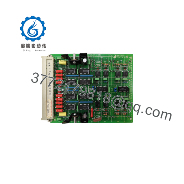
812.06.00
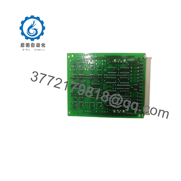
812.06.00
Stage 2: Removing the Old Module — Approximately 5 Minutes
- Confirm zero-energy state using the site’s electrical safety procedure.
- Remove the front bezel, retaining hardware, or card cover as applicable.
- Label each cable before disconnecting it.
- Disconnect wiring without pulling on individual conductors.
- Release the card retention mechanism.
- Pull the board straight out from the card cage or connector assembly.
- Inspect the mating connector and backplane for bent contacts, contamination, oxidation, or mechanical damage.
- Place the removed card in an ESD-safe bag.
⚠️ Keep the old 812.06.00 installed board available for comparison. Do not discard it immediately. It provides the most reliable reference for switch settings, board revision, connector orientation, and field wiring.
Stage 3: Installing the New Module — Approximately 5–10 Minutes
- Verify the replacement label against the removed card. Confirm 812.06.00 and any suffix/revision markings.
- Put on the grounded ESD strap before handling the PCB.
- Compare connector positions and board geometry.
- Clone all DIP-switch and jumper settings from the documented original configuration.
- Pay particular attention to address, termination, operating-mode, and configuration selectors where fitted.
- Insert the card straight into the chassis connector.
- Confirm that the retaining mechanism fully engages.
- Reconnect each cable according to the photographs and labels.
- Tighten terminals using the applicable manufacturer torque specification.
Self-Checklist:
- Exact model number verified
- Hardware revision compared
- DIP switches copied
- Jumpers copied
- Connector positions verified
- Wiring labels checked
- Retention tabs locked
- No foreign material in connector area
Stage 4: Power-On & Testing — Approximately 10–15 Minutes
- Perform a pre-power inspection.
- Check the relevant power rails for shorts using the site’s approved electrical test procedure.
- Energize the control rack according to the equipment manual.
- Observe all card and system status indicators.
- Record the startup state before changing configuration.
- Check controller diagnostics for card recognition or configuration faults.
- Compare the detected hardware identity with the expected 812.06.00 configuration.
- Verify communication with the associated control system.
- Run an I/O or functional simulation where the application permits.
- Return field devices to service only after the control-system diagnostics remain normal.
⚠️ Do not assume a red fault indication means firmware mismatch. On legacy Reliance equipment, a fault can also result from incorrect card configuration, connector problems, incompatible hardware revision, missing system configuration, or a failed mating board.
Incoming Quality-Control Procedure
For surplus or replacement inventory, the inspection sequence should be documented rather than represented as an undocumented blanket guarantee.
1. Inbound Inspection & Traceability
- Verify supplier documentation, packing information, and part-number traceability where available.
- Check serial-number markings and manufacturer labels.
- Inspect for corrosion, damaged connectors, scratches, rework evidence, contamination, or UV-related discoloration.
- Check supplied accessories against the purchase description.
- Photograph the board before functional testing.
2. Functional Testing
Use a known-good Reliance Electric-compatible test rack or an OEM-approved simulation environment appropriate to the specific PSIC application.
- Confirm power-up behavior.
- Record LED/status indications.
- Verify card recognition.
- Check applicable control-system communications.
- Exercise available functions under controlled conditions.
- Perform extended powered operation where the test fixture supports it.
- Record test results in an equipment-specific Test Report.
Do not claim a 24-hour load test unless that test was actually performed on the individual unit.
3. Electrical Testing
Where applicable and permitted by the equipment documentation:
- Insulation resistance testing using an appropriate test voltage
- Ground/bond continuity verification
- Dielectric withstand testing only where the board design and OEM procedure explicitly permit it
⚠️ Do not apply a 500 V Megger or perform hipot testing indiscriminately to an electronic PCB. Semiconductor devices and connected circuitry can be damaged by inappropriate insulation-test voltages.
4. Firmware and Configuration Verification
- Record firmware or onboard revision information if accessible.
- Photograph DIP switches and jumpers.
- Record hardware revision and serial number.
- Preserve configuration information before shipment when the unit is supplied as a tested replacement.
5. Final QC and Packaging
- QC inspector records the final inspection result.
- Place the PCB in ESD-safe packaging.
- Use cushioning suitable for the board and connector assemblies.
- Use a rigid corrugated shipping carton.
- Attach the inspection record or QC identification label.
Test photographs and functional-test records should be supplied upon request when those records actually exist for the specific unit.
Frequently Asked Questions (FAQ)
Can the Reliance 812.06.00 be hot-swapped under power?
Do not assume that it can. The available references identify the 812.06.00 as a PSIC control card, but they do not establish a universal hot-swap procedure. Unless the specific Reliance Electric chassis documentation explicitly permits energized card removal, shut down and isolate the equipment before removing the board.
Is the Reliance 812.06.00 obsolete?
It should be treated as a legacy/obsolete-equipment spare for procurement planning. Current availability is primarily represented through surplus, replacement, and repair channels rather than a conventional current-production distribution network.
Is 812.06.00 the same as GD.720.06.00-A?
Multiple independent industrial automation references associate 812.06.00 with GD.720.06.00-A, and repair suppliers identify GD.720.06.00-A specifically as a Reliance PSIC control card.
For a live replacement, however, compare the complete markings on the installed board. Do not treat an online cross-reference as sufficient evidence of interchangeability.
Will I lose the PLC or control-system program when replacing this card?
Not necessarily. The answer depends on where the application configuration and control logic reside. A board-level replacement does not automatically mean that the complete control program is erased, but configuration associated with the card may need to be restored.
Back up the existing system before removing the card. Photograph hardware settings and record diagnostics. If the 812.06.00 is part of a larger legacy Reliance control architecture, confirm the configuration-retention mechanism from the applicable system manual.
Why do some listings describe 812.06.00 as an analog input module?
There are conflicting third-party listings. One supplier describes it as a 16-channel analog input module, while multiple independent sources identify 812.06.00 / 812.06.00A / GD.720.06.00-A as a PSIC control card.
For procurement, use the physical board label, connector arrangement, hardware revision, and the original system documentation to resolve the discrepancy. Do not purchase the part based solely on an online description of its I/O count.
What condition should I expect when buying a surplus 812.06.00?
Condition must be stated explicitly. Acceptable descriptions include New Original / New Surplus, Factory Sealed, or Refurbished / Tested. Do not treat “in stock” as proof of new-original condition. The seller should provide photographs of the actual unit, including labels and revision markings, when condition is important to the application.
What should I verify before ordering?
Send the supplier the complete information from the installed board:
- 812.06.00 base model
- Any suffix, such as 812.06.00A
- GD.720.06.00-A marking, if present
- Hardware revision
- Serial number
- Connector and board photographs
- Existing system/chassis identification
That verification step is inexpensive compared with discovering an incompatibility after a production shutdown. Independent repair references also confirm that 812.06.00 is handled as a PSIC board, with GD.720.06.00-A listed as a related Reliance PSIC control-card reference.



