
 WhatsApp: +86 16626708626
 Email:
  Phone: +86 16626708626
Description
Key Technical Specifications
| Parameter | Specification |
| Part Number | 0-51851-5 (CRCF Configuration) |
| System Compatibility | Reliance Electric MaxPak Plus V*S Drives & Spindle Controllers |
| Control Interfaces | 8 Front Faceplate Rotary Dial Potentiometers (0 to 10 Scale) |
| Adjustable Parameters | Max Speed, Min Speed, Acceleration, Deceleration, Jog Speed, Current Limit, IR Comp, Stability |
| Backplane Connection | Rear edge-finger connector with gold-plated contact tabs |
| Circuit Design | 6 Integrated Circuits, discrete transistors, metal film/carbon resistors |
| Operating Temperature | 0°C to +55°C |
| Form Factor | Plug-in regulator card with attached metal faceplate |
Product Introduction & Supply Chain Strategy
The Reliance Electric 0-51851-5 is a CRCF regulator control board engineered for MaxPak Plus and V*S spindle drives. It provides speed tuning, current limiting, acceleration/deceleration control, and IR compensation for industrial motor drive systems.
Procuring this module as New Surplus ensures immediate system recovery during unscheduled drive downtime, bypassing long factory lead times for discontinued legacy hardware. Selecting genuine New Surplus over high-risk refurbished boards avoids degraded potentiometers, dried capacitors, and thermal-stressed logic circuits, keeping production lines active while minimizing Total Cost of Ownership (TCO).
Installation & Configuration Guide
Stage 1: Pre-Installation (Prep & Safety)
- Disconnect main AC supply voltage to the drive chassis and perform complete Lock-Out/Tag-Out (LOTO).
- Put on a grounded ESD wrist strap connected to the metal chassis.
- Document the exact dial settings (0 to 10 values) for all 8 front-panel potentiometers on the existing board.
Stage 2: Removal
- Unfasten panel retaining screws securing the 0-51851-5 faceplate to the drive rack.
- Pull the card straight out from the chassis guide rails to disengage the rear edge connector without twisting.
- Inspect the rack socket for debris or damaged connector contacts.
Stage 3: Installation (Clone & Seat)
- Adjust the 8 front dials on the new 0-51851-5 board to match the original unit settings (Max Spd, Min Spd, Accl, Decl, Jog Spd, Cur Lim, IR Comp, Stab).
- Align the board edges with the card guide rails and slide the module into the slot.
- Press firmly until the rear edge fingers seat completely into the receptacle connector, then tighten retaining screws.
Stage 4: Power-On & Testing
- Apply power to the drive enclosure and verify drive status indicators show no fault codes.
- Run the motor at low speed to confirm stable velocity regulation and fine-tune IR compensation or stability dials if minor hunting occurs.
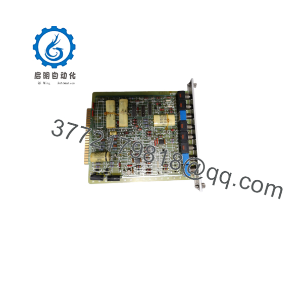
0-51851-5
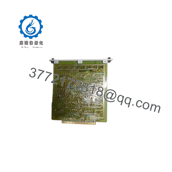
0-51851-5
Firmware/Software Versions & Upgrade Notes
- Hardware Revisions: Ensure the sub-type code matches your drive cabinet documentation. While the main PCB layout remains constant across 0-51851 variants, specific CRCF potentiometer ranges are tailored to motor rating groups.
- Tuning Precision: Do not perform hardware swaps without mirroring dial settings. Mismatched current limit or acceleration rates will cause drive trips or mechanical shock to connected machinery upon start-up.
- Replacement Warning: Avoid using power tools on front-panel dials; manually adjust potentiometers with a standard tuning screwdriver to prevent internal wiper shaft damage.
Frequently Asked Questions (FAQ)
Q: Is this Reliance Electric 0-51851-5 board brand new?
A: Yes. This module is 100% New Surplus / Original New stock. It has never been installed in an active drive cabinet, pulled from a decommissioned plant, or repaired.
Q: Why choose New Surplus over a refurbished regulator board?
A: Refurbished drive boards often contain worn rotary potentiometers that develop dead spots, causing speed drift or erratic current spikes. New Surplus guarantees factory-fresh potentiometers, pristine edge connector plating, and predictable long-term drive stability.
Q: How is this legacy Reliance card verified prior to shipment?
A: Every 0-51851-5 card undergoes visual component inspection, edge connector continuity checks, and physical dial mechanism testing in an ESD-safe facility prior to dispatch.
Q: Can I insert or extract the 0-51851-5 card while the drive is powered?
A: No. Always isolate line power to the drive before inserting or removing the regulator board. Live insertion can cause electrical arcing across edge contacts, damaging the drive backplane and onboard logic ICs.
Q: What warranty coverage comes with this New Surplus card?
A: All New Surplus items come with a comprehensive 1-year functional replacement warranty. If any functional defect arises under normal operating conditions, we supply an immediate direct replacement or process a full credit.



