WhatsApp: +86 16626708626
 Email:
 Phone: +86 16626708626
Description
Core Product Summary (Brand / Model / Key Attributes)
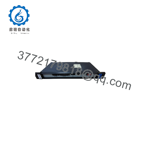
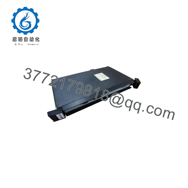
The Reliance Electric 0-57404-1E is a rack-mounted industrial control and digital output printed circuit board assembly engineered for deployment within Reliance Electric AutoMax distributed control and automation platforms. Designed to install directly into a standard AutoMax chassis backplane, this module translates control commands from the system processor into discrete output signals for field actuators, relays, and pilot devices.
Constructed with an integrated front faceplate, status indicators, and rear backplane edge connector, the 0-57404-1E (representing revision -1E of the 0-57404 hardware assembly) integrates into modular Reliance control cabinets used in continuous manufacturing, drive coordination, and process automation. Maintenance and procurement teams verify both the base 0-57404 part number and the -1E revision suffix to maintain hardware and firmware compatibility across existing system racks.
Key Technical Specifications
| Parameter | Verified Specification |
| Manufacturer / Brand | Reliance Electric (Rockwell Automation / Reliance Automation) |
| Model / Order Number | 0-57404-1E (base part number 0-57404, revision suffix -1E) |
| Product Type | Industrial Control / Digital Output Module Assembly |
| System Compatibility | Reliance Electric AutoMax Distributed Control / Automation Platform |
| Mounting Type | Rack-mounted plug-in module for AutoMax chassis backplane |
| Indicators | Front-panel diagnostic and channel status LEDs |
Detailed Product Overview
In Reliance Electric AutoMax control architectures, modular card racks distribute central processing, network communication, and discrete field I/O handling across dedicated plug-in circuit boards. The Reliance Electric 0-57404-1E operates as a rack-mounted output interface within this chassis structure, receiving logic-level commands across the backplane data bus and switching field circuits connected at the front interface.
Because Reliance Electric AutoMax assemblies carry specific hardware revision suffixes—such as -1E on the 0-57404-1E—component layouts, output driver ratings, and timing characteristics can differ across iterations. Confirming that the replacement board matches the exact -1E suffix stamped on the faceplate and PCB label helps ensure electrical and configuration alignment alongside existing AutoMax processor and I/O modules.
0-57404-1E
0-57404-1E
Engineering Selection Highlights
- Exact Base & Revision Match (
0-57404-1E): Identified by base number0-57404with revision suffix-1E→ Verify the complete part number and revision code on the existing module faceplate before ordering to prevent hardware or field-wiring mismatches. - Reliance AutoMax Rack Architecture Fit: Engineered for plug-in installation inside Reliance AutoMax card-file chassis → Confirm target slot assignment and backplane compatibility in your cabinet documentation prior to installation.
- Modular Card-Rack Handling: Built as a printed circuit board assembly with a front faceplate and rear edge connector → Requires electrostatic discharge (ESD) precautions and full rack power isolation during removal or insertion.
System Compatibility & Integration Requirements
| Item / Dependency | Verified Compatibility or Requirement | Practical Note |
| Control System Platform | Reliance Electric AutoMax Control Architecture | Intended for native integration within compatible Reliance Electric card-file racks. |
| Backplane Interface | Dedicated chassis card slot edge connector | Inspect backplane pins and board edge contacts for alignment and cleanliness before seating. |
| Hardware Revision Level | Revision -1E (0-57404-1E) |
Match the exact revision suffix when replacing boards in active system racks. |
Dimensions, Mounting & Connection Notes
- Form Factor: Modular rack-mounted printed circuit board assembly with a front faceplate designed for insertion into standard Reliance Electric AutoMax chassis slots.
- Handling Precautions: Static-sensitive integrated circuits are mounted across the PCB surface. Use grounded ESD wrist straps and handle the module by its faceplate or board edges.
- Power Isolation: De-energize the host control rack and isolate external field I/O power following site lockout/tagout (LOTO) procedures before removing or seating rack modules.
FAQ
What is the Reliance Electric 0-57404-1E?
The Reliance Electric 0-57404-1E is a rack-mounted industrial control and digital output printed circuit board assembly used within Reliance Electric AutoMax automation systems.
Which control system platform uses the 0-57404-1E module?
It is designed for deployment in Reliance Electric AutoMax modular rack-based distributed control and drive-control architectures.
What does the -1E suffix on 0-57404-1E indicate?
The -1E suffix identifies the specific hardware revision level of the 0-57404 module assembly; matching this revision ensures compatibility with the host rack, field wiring, and existing project configuration.
Verification & Troubleshooting Notes
- Faceplate & Revision Verification: Before installing a spare 0-57404-1E unit, compare the base part number (
0-57404), revision suffix (-1E), and any secondary board stickers against the original module and cabinet bill of materials. - Backplane Seating & LED Check: If a rack fault or output switching error occurs after installation, isolate rack and field power, verify that the module is fully seated and latched into the backplane connector, and observe front-panel status indicators upon power restoration.
- Safe Maintenance Protocol: Always follow facility electrical safety and lockout/tagout procedures before servicing internal control cabinet hardware or field terminal wiring.