WhatsApp: +86 16626708626
 Email:
 Phone: +86 16626708626
Description
Core Product Summary (Brand / Model / Key Attributes)
The Reliance Electric 0-57411-2C (also referenced under base part number 57411 or 57C411, with revision suffix -2C) is a rack-mounted Resolver Input Module designed for Reliance Electric AutoMax PLC and DCS 5000 distributed control systems. Functioning as a resolver-to-digital (R/D) position feedback interface, the module converts analog sine and cosine signals from a rotary resolver into digital angular position data for closed-loop motion, speed, and synchronization control.
Built around a tracking resolver-to-digital converter, the module delivers 12-bit angular resolution per electrical revolution paired with a 2-bit revolution counter, and supports programmable position sampling periods ranging from 500 microseconds to 32.767 seconds. It operates with a 2381 Hz excitation frequency and a 26/11.8 transformer ratio, installing into a standard AutoMax / DCS 5000 Multibus backplane slot with front faceplate retention hardware and diagnostic status LEDs.
Key Technical Specifications
| Parameter | Verified Specification |
| Manufacturer / Brand | Reliance Electric (Rockwell Automation) |
| Model / Order Number | 0-57411-2C (base series 57411 / 57C411; revision suffix -2C) |
| Product Type | Resolver Input Module (Resolver-to-Digital Converter) |
| Compatible Control Systems | Reliance Electric AutoMax PLC / DCS 5000 |
| Position Resolution | 12-bit per electrical revolution + 2-bit revolution counter |
| Sampling Period | Programmable from 500 microseconds to 32.767 seconds |
| Excitation Frequency | 2381 Hz |
| Transformer Ratio | 26 / 11.8 |
| Minimum Rotor Impedance | 400 Ω |
| External Synchronization | External strobe input supported |
| Operating Temperature | 0°C to 60°C |
| Storage Temperature | -40°C to 85°C |
| Approximate Dimensions | 11.75 in × 1.25 in × 7.375 in (H × W × D) |
| Mounting Type | Plug-in rack module for AutoMax / DCS 5000 Multibus backplane |
| Reference Documentation | Instruction Manual J-3640 |
Detailed Product Overview
In multi-axis drive coordination, web-handling, and continuous process lines controlled by Reliance Electric AutoMax or DCS 5000 racks, accurate rotary shaft position feedback is required for electronic line-shafting and closed-loop positioning. The Reliance Electric 0-57411-2C Resolver Input Module provides this feedback interface by exciting an external brushless resolver and decoding its returning rotor signals into digital counts accessible over the rack backplane.
Internally, the module employs a tracking resolver-to-digital converter that continuously tracks shaft rotation, generating a 12-bit digital word representing angular position within a single electrical revolution alongside a 2-bit revolution counter. Depending on application timing requirements, the host processor can sample the converted position data across a software-configurable interval spanning from 500 microseconds up to 32.767 seconds, or synchronize captures using the module’s external strobe input.
Physically, the 0-57411-2C consists of a printed circuit board housed within a protective enclosure and fitted with a full-height front faceplate. Top and bottom extraction tabs and retention screws secure the card into the Multibus I/O backplane of an AutoMax or DCS 5000 card storage rack, while front-panel LEDs indicate rotation direction, feedback integrity, common clock status, isolated power supply health, and general module status.
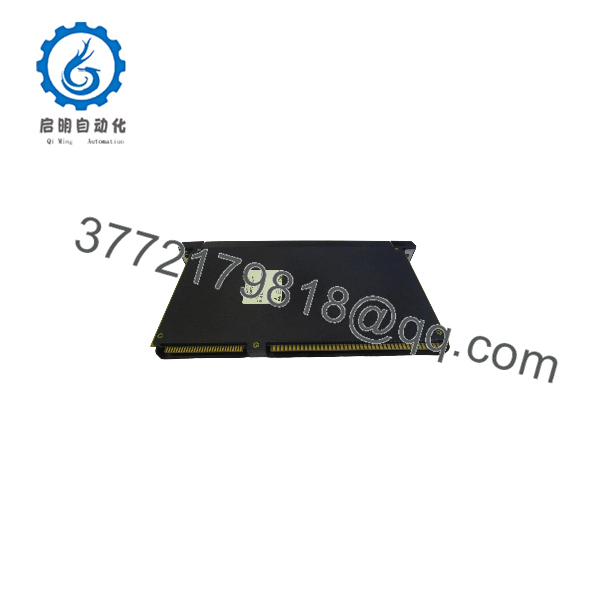
0-57411-2C
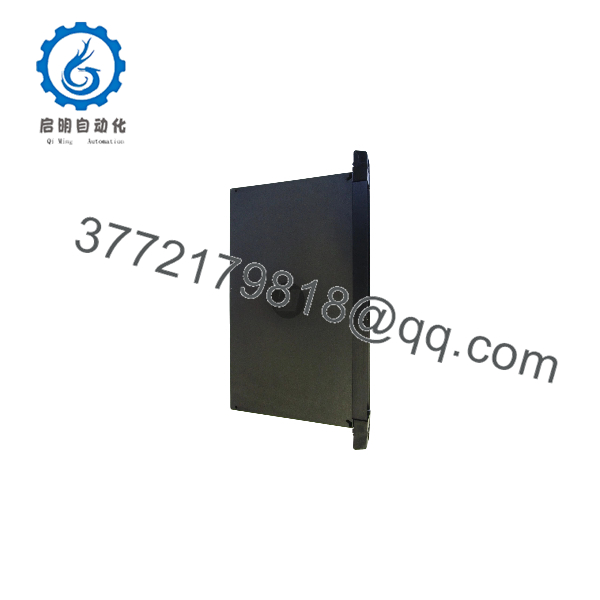
0-57411-2C
Engineering Selection Highlights
- AutoMax & DCS 5000 Rack Fit: Engineered specifically for Reliance Electric AutoMax PLC and DCS 5000 Multibus card racks → Confirm that the host chassis has an available I/O slot and supports the 57411/57C411 hardware family before ordering.
- Resolver Electrical Match (26/11.8 Ratio, 2381 Hz, 400 Ω Min. Rotor Impedance): Built for resolvers compatible with a 26/11.8 transformer ratio, 2381 Hz excitation frequency, and at least 400 Ω rotor impedance → Verify connected field resolver nameplate specifications so excitation loading and secondary signal levels stay within module limits.
- 12-Bit Resolution with External Strobe Support: Provides 12-bit single-turn resolution, a 2-bit revolution counter, and programmable sampling down to 500 µs → Suitable for applications requiring deterministic angular position tracking or hardware-synchronized position latching via an external strobe signal.
- Exact Revision Suffix (
-2C): Part of the0-57411(57C411) module line where letter suffixes (-2A,-2C,-2E,-2F,-2L) denote hardware revisions → Match the exact-2Csuffix printed on the existing module label to maintain consistency with installed rack hardware and configuration files.
System Compatibility & Integration Requirements
| Item / Dependency | Verified Compatibility or Requirement | Practical Note |
| Control System Platform | Reliance Electric AutoMax PLC / DCS 5000 | Installs directly into the Multibus I/O backplane of a compatible card storage rack. |
| Field Transducer | Brushless Rotary Resolver | Must match 2381 Hz excitation, 26/11.8 transformer ratio, and ≥ 400 Ω minimum rotor impedance. |
| Field Cabling | Twisted-pair shielded cabling | Recommended for both excitation and sine/cosine feedback runs to minimize noise pickup. |
| Hardware Revision | Base 0-57411 / 57C411, Revision -2C |
Verify suffix -2C against the existing faceplate label during spare-parts replacement. |
Dimensions, Mounting & Connection Notes
- Dimensions: Approximately 11.75 in × 1.25 in × 7.375 in (H × W × D).
- Mechanical Mounting: Single-slot plug-in module that seats into the AutoMax / DCS 5000 rack backplane and fastens via front faceplate retention screws; equipped with top and bottom faceplate tabs for card extraction.
- Field Wiring: Connects to the field resolver using twisted-pair wiring for excitation reference and sine/cosine feedback lines; route resolver signal cables away from high-voltage motor armature or AC power conductors.
- Safety & Handling Precautions: De-energize the host rack according to site lockout/tagout (LOTO) procedures before inserting or removing the module, and observe standard electrostatic discharge (ESD) precautions when handling the assembly outside the chassis.
FAQ
What is the Reliance Electric 0-57411-2C? The Reliance Electric 0-57411-2C is a rack-mounted Resolver Input Module (also referenced under base code 57411 or 57C411) that converts analog rotary resolver signals into 12-bit digital angular position data for Reliance AutoMax and DCS 5000 control systems.
What position resolution and sampling rates does the 0-57411-2C provide? It provides 12-bit resolution per electrical revolution along with a 2-bit revolution counter, and supports programmable sampling periods from 500 microseconds to 32.767 seconds.
What resolver electrical parameters are required for this module? The module operates at a 2381 Hz excitation frequency with a 26/11.8 transformer ratio and requires a minimum resolver rotor impedance of 400 Ω.
What do the front-panel LEDs on the 0-57411-2C indicate? The faceplate status LEDs indicate rotation direction, resolver feedback status, common clock presence, isolated internal power supply status, and overall module health.
Which instruction manual covers the 0-57411-2C Resolver Input Module? Hardware installation, wiring, and register details for the 57411 / 0-57411 resolver input module series are documented in Reliance Electric Instruction Manual J-3640.
Verification & Troubleshooting Notes
- Faceplate LED Inspection: During operation, check the front-panel status LEDs to confirm isolated power supply operation, common clock presence, feedback signal integrity, and rotation direction indication.
- Resolver Wiring & Impedance Check: If feedback fault indicators illuminate or position counts fail to update, isolate power and verify continuity, shield grounding, and rotor impedance (minimum 400 Ω) across the twisted-pair resolver excitation and sine/cosine feedback cables.
- Backplane Seating & Revision Match: Confirm that the replacement unit carries the exact
0-57411-2C(or57C411-2C) designation and is fully seated into the Multibus backplane connector with top and bottom faceplate screws secured before re-energizing the rack.