
 WhatsApp: +86 16626708626
 Email:
 Phone: +86 16626708626
Description
Core Product Summary (Brand / Model / Key Attributes)
The Reliance Electric 0-60023-5 is an AC Power Technology Module built for the Reliance AutoMax Distributed Power System (DPS) and SA3000 Power Module Interface (PMI) drive control architecture. Installed directly into a PMI rack, this circuit card bridges the control processor and the AC power stage by comparing torque and flux current reference commands against real-time motor and inverter feedback to generate torque and flux voltage references.
The assembly features a rectangular printed circuit board mounted to a metal faceplate equipped with top and bottom locking set screws, a green operational status LED indicator, a Power Module Interface connector, and Synchronous Transfer communication ports. It processes motor voltage, motor current, DC bus voltage and current, ground current, temperature, and inverter fault feedback while incorporating an onboard watchdog timer for hardware fault monitoring.
Key Technical Specifications
| Specification Category | Verified Technical Parameter |
| Manufacturer / Brand | Reliance Electric |
| Model / Order Number | 0-60023-5 (B/M 0-60023 series) |
| Product Type | AC Power Technology Module |
| System Family | AutoMax Distributed Power System (DPS) / SA3000 Power Module Interface (PMI) |
| Primary Function | Torque and flux current regulation; AC power module feedback and reference interfacing |
| Supported Feedback Signals | Motor voltage/current, DC bus voltage/current, ground current, temperature, inverter fault |
| Front-Panel Connectors | Power Module Interface connector, Synchronous Transfer communication ports (In/Out) |
| Status Indicator | Green “OK” LED indicator |
| Integrated Protection | Onboard watchdog timer; ground current fault threshold monitoring |
| Mounting Style | Rack-mounted plug-in module with faceplate locking screws |
Detailed Product Overview
Within the Reliance Electric AutoMax Distributed Power System, the 0-60023-5 AC Power Technology Module serves as the dedicated regulator interface between the digital control rack and the AC drive power stage. During real-time AC drive operation, the module receives torque and flux current reference values from the PMI processor and compares them against incoming electrical and thermal measurements from the connected power module. Based on this comparison, it produces the torque and flux voltage reference signals required to govern inverter output.
To maintain closed-loop drive regulation and protection, the board monitors multiple feedback channels simultaneously, including three-phase motor voltage and current, DC bus voltage and current, ground fault current, thermal conditions, and inverter fault status. An integrated watchdog timer continuously supervises module execution, while synchronous transfer ports allow coordinated signal exchange across multi-unit or transfer-capable drive configurations.
Structurally, the 0-60023-5 consists of a dual-sided populated circuit board secured to a narrow rack faceplate. The rear edge plugs into the PMI rack backplane, while front-accessible ports and two captive faceplate set screws allow technicians to secure the module mechanically and connect external interface harnesses cleanly inside industrial drive cabinets.
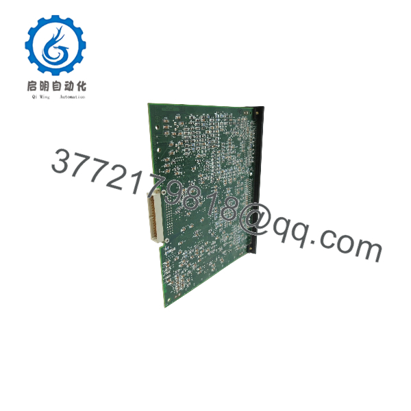
0-60023-5
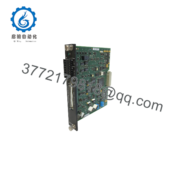
0-60023-5
Engineering Selection Highlights
- Exact Architecture Fit: Engineered specifically for AutoMax Distributed Power System (DPS) and SA3000 Power Module Interface (PMI) racks managing AC drive power stages, rather than general-purpose PLC I/O slots.
- Closed-Loop AC Regulation Role: Performs real-time torque and flux current comparison against feedback data, making it essential for vector-controlled AC drive installations using the SA3000 PMI platform.
- Comprehensive Feedback Handling: Consolidates motor, DC bus, ground current, temperature, and inverter fault feedback onto a single interface card, reducing external signal-conditioning hardware.
- Synchronous Transfer Support: Equipped with dedicated Synchronous Transfer ports on the faceplate to support applications requiring coordinated power-source or drive-bus transfer timing.
- Positive Mechanical Retention: Includes top and bottom faceplate set screws and a front-panel green status indicator to verify firm rack seating and normal module readiness.
System Compatibility & Integration Requirements
| Item / Dependency | Verified Compatibility or Requirement | Practical Note |
| Control Architecture | Reliance AutoMax Distributed Power System (DPS) | Operates alongside the PMI Processor and Universal Drive Controller (UDC) tasks in real-time drive control loops. |
| Chassis / Rack System | SA3000 Power Module Interface (PMI) Rack | Must be installed in its designated PMI rack slot and mated securely to the backplane connector. |
| Power Stage Interface | Compatible Reliance AC Power Modules (SA3000 series architecture) | Connects via the front Power Module Interface port to exchange voltage, current, thermal, and fault signals. |
| Synchronous Transfer | External Synchronous Transfer wiring (when used) | Utilizes the front In/Out Synchronous Transfer communication ports for coordinated transfer setups. |
| Safety Circuitry | External hardwired emergency stop circuit | System installation requires an independent, hardwired stop circuit outside the drive control electronics. |
Dimensions, Mounting & Connection Notes
- Mounting Configuration: Slides into a standard slot in the SA3000 Power Module Interface (PMI) rack and locks into place using two captive set screws at the top and bottom of the faceplate.
- Backplane & Front Connections: Interfaces with internal rack power and data buses through its rear backplane connector; external drive harnesses attach to the female Power Module Interface port and Synchronous Transfer ports on the front panel.
- Wiring Separation & Grounding: Low-voltage control and feedback wiring routed inside the power module enclosure must be kept physically separated from uninsulated live power parts and high-voltage conductors in accordance with local electrical codes.
- ESD & Capacitor Safety: Observe electrostatic discharge (ESD) precautions when handling the exposed PCB assembly, and verify that DC bus capacitors have fully discharged before connecting or disconnecting interface cables.
FAQ
What is the Reliance Electric 0-60023-5?
The Reliance Electric 0-60023-5 is an AC Power Technology Module used in AutoMax Distributed Power System (DPS) installations to interface the Power Module Interface (PMI) rack with an AC drive power module.
What function does the 0-60023-5 perform during drive operation?
It compares torque and flux current reference data from the PMI processor against live motor, DC bus, ground current, and temperature feedback to generate torque and flux voltage references for AC drive control.
Which connections are located on the faceplate of the 0-60023-5?
The faceplate features a Power Module Interface connector, Synchronous Transfer communication ports, a green “OK” status LED, and two locking set screws.
What feedback signals does this module monitor?
It supports motor voltage and current, DC bus voltage and current, ground current, temperature, and inverter fault feedback signals.
Does the 0-60023-5 include built-in fault monitoring?
Yes, the module includes an onboard watchdog timer, ground current fault threshold monitoring, and a front-panel green “OK” LED indicator to signal operational status.
Verification & Troubleshooting Notes
- Front-Panel Status LED Check: Verify that the green “OK” LED on the faceplate illuminates under normal powered operation; an unlit indicator may point to missing rack backplane power, an unseated backplane connector, or an internal watchdog fault.
- Mechanical & Cable Seating: Confirm both faceplate set screws are tightened evenly and inspect the Power Module Interface and Synchronous Transfer connectors for bent pins, loose latches, or harness strain.
- Feedback & Ground Fault Isolation: If inverter fault or ground current trips occur, inspect external feedback cabling and power-stage sensors before replacing the board, as external ground leakage or overtemperature conditions trigger valid protective faults through this interface.
- Hazardous Voltage Precaution: Always isolate incoming AC/DC power and confirm DC bus capacitors are safely discharged before removing or installing the module in a live drive cabinet.



