WhatsApp: +86 16626708626
 Email:
 Phone: +86 16626708626
Description
Core Product Summary (Brand / Model / Key Attributes)
The Reliance Electric 0-60031-5 is a Resolver & Drive I/O Module built for the Reliance AutoMax Distributed Power System (DPS) and SA3000 Power Module Interface (PMI) rack architecture. Installed in a dedicated PMI chassis slot, this card interfaces field position and speed sensors with the drive control processor while handling auxiliary drive input and output signals.
The assembly integrates a resolver-to-digital feedback circuit capable of 12-bit or 14-bit position resolution, an analog tachometer input channel, an external strobe input for position capture, and discrete drive I/O points. Its narrow metal faceplate houses two female plug connectors labeled for resolver feedback and drive I/O, alongside nine front-panel status LED indicators for hardware and signal monitoring.
Key Technical Specifications
| Specification Category | Verified Technical Parameter |
| Manufacturer / Brand | Reliance Electric |
| Model / Order Number | 0-60031-5 (B/M 0-60031 series) |
| Product Type | Resolver & Drive I/O Module |
| System Family | AutoMax Distributed Power System (DPS) / SA3000 Power Module Interface (PMI) |
| Rack Slot Assignment | Slot C3 (in 4-slot and 8-slot PMI racks) |
| Resolver Feedback Resolution | 12-bit or 14-bit selectable data format |
| Analog Input | 1 channel (supporting analog tachometer feedback) |
| Special Digital Input | External strobe input for position latching |
| Front-Panel Connectors | 1 Resolver Feedback port; 1 Drive I/O port |
| Status Indicators | 9 front-panel LED indicators (green and red status LEDs) |
| Mounting Style | Rack-mounted plug-in module with faceplate mounting screws |
Detailed Product Overview
Within the Reliance Electric AutoMax Distributed Power System, the 0-60031-5 Resolver & Drive I/O Module serves as the primary electromechanical feedback and auxiliary discrete/analog I/O interface inside the SA3000 Power Module Interface (PMI) rack. During closed-loop motor control, the card supplies excitation to a rotary resolver and converts returning sine and cosine signals into digital angular position data in either 12-bit or 14-bit mode for the PMI processor and Universal Drive Controller (UDC) tasks.
In addition to rotor position tracking, the module consolidates essential drive-level interface circuits onto a single rack slot. It accepts an analog input for tachometer speed feedback and includes a high-speed external strobe input circuit that latches instantaneous resolver position data on an external trigger event. Dedicated drive I/O circuitry handles discrete control inputs and outputs between external machine interlocks or auxiliary controls and the drive rack.
Structurally, the 0-60031-5 is built on a printed circuit card attached to a narrow rack faceplate. The rear edge connector mates with the PMI backplane for power and internal bus communication, while two front-panel female connectors separate resolver feedback wiring from drive I/O cabling. Nine LED indicators arranged along the faceplate give technicians immediate visibility into board power, operational state, and fault conditions.
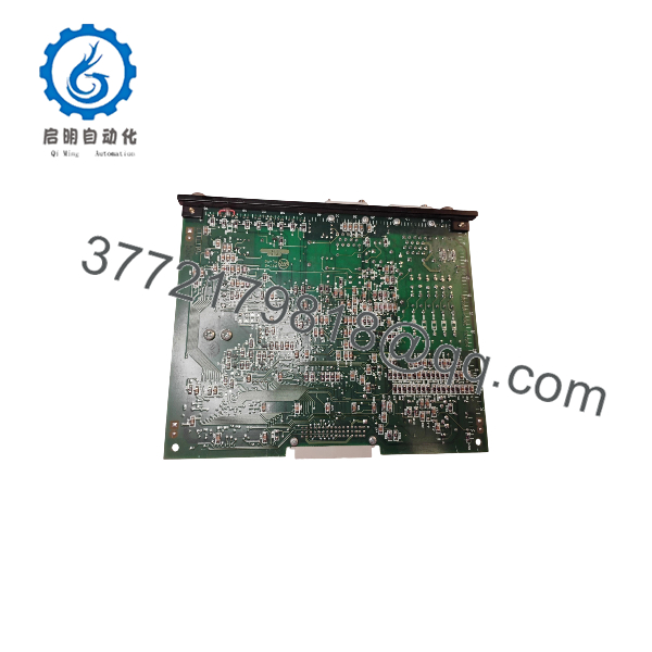
0-60031-5
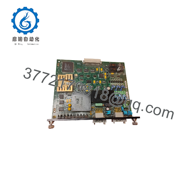
0-60031-5
Engineering Selection Highlights
- Dedicated PMI Rack Slot Fit: Engineered specifically for Slot C3 of Reliance SA3000 Power Module Interface (PMI) 4-slot and 8-slot racks, sitting between the PMI Processor (Slot C2) and the A-C Power Technology Module (Slot C4).
- Selectable Resolver Resolution: Supports both 12-bit and 14-bit resolver data modes, allowing integration with standard and higher-resolution positioning applications within the SA3000 drive architecture.
- Integrated Tachometer & Strobe Inputs: Combines an analog tachometer input and an external strobe trigger input on the same card as the resolver interface, minimizing extra I/O hardware for speed feedback and registration capture.
- Separated Field Connections: Uses two distinct front-panel connectors for Resolver Feedback and Drive I/O to keep low-level sensor signals physically separated from general drive I/O wiring.
- Multi-LED Front Diagnostics: Features nine front-panel status LEDs paired with UDC status registers to simplify commissioning and fault isolation during drive setup.
System Compatibility & Integration Requirements
| Item / Dependency | Verified Compatibility or Requirement | Practical Note |
| Control Architecture | Reliance AutoMax Distributed Power System (DPS) | Operates in coordination with the PMI Processor (B/M 0-60021) and Universal Drive Controller (UDC) software tasks. |
| Chassis / Rack System | SA3000 Power Module Interface (PMI) 4-Slot or 8-Slot Rack | Installed in designated Slot C3; 8-slot racks are used for High Power SA3000 drive configurations. |
| Power Source | PMI Rack Power Supply (B/M C-60007) via backplane | Draws operating power directly from the PMI rack backplane bus. |
| Companion Rack Modules | PMI Processor (Slot C2) and A-C Power Technology Module (B/M 0-60023, Slot C4) | Forms the core four-module control set alongside the rack power supply in Slot C1. |
| Field Feedback Devices | Brushless resolver and/or analog tachometer | Requires proper shield termination and resolver balance/gain calibration during commissioning. |
Dimensions, Mounting & Connection Notes
- Rack Placement: Slides into Slot C3 of the SA3000 Power Module Interface (PMI) rack and secures to the chassis frame using top and bottom faceplate screws.
- Front-Panel Connectors: Equipped with two female plug connectors on the lower half of the faceplate—one dedicated to Resolver Feedback and one dedicated to Drive I/O.
- Signal Wiring Precautions: Route resolver feedback cables separately from high-voltage power conductors and motor leads to prevent electrical noise from distorting sine/cosine feedback signals.
- Calibration & Handling: Observe electrostatic discharge (ESD) precautions when handling the circuit board outside the rack, and perform resolver balance and gain calibration according to system setup procedures when replacing the module or resolver.
FAQ
What is the Reliance Electric 0-60031-5?
The Reliance Electric 0-60031-5 is a Resolver & Drive I/O Module used in AutoMax Distributed Power System (DPS) and SA3000 Power Module Interface (PMI) racks to process motor position/speed feedback and drive I/O signals.
Which slot does the 0-60031-5 occupy in a PMI rack?
It installs into Slot C3 in both 4-slot and 8-slot SA3000 Power Module Interface (PMI) racks, positioned between the PMI Processor in Slot C2 and the A-C Power Technology Module in Slot C4.
What resolver resolution does the 0-60031-5 support?
The module supports both 12-bit and 14-bit resolver data formats.
Does the 0-60031-5 support analog tachometer or strobe signals?
Yes, in addition to resolver feedback and discrete drive I/O, the module includes an analog input for tachometer feedback and an external strobe input circuit for capturing position data.
What connectors and indicators are on the faceplate of the 0-60031-5?
The faceplate features two female plug connectors labeled for Resolver Feedback and Drive I/O, along with nine LED status indicators.
Verification & Troubleshooting Notes
- Front-Panel LED & Register Check: Inspect the nine LED indicators on the faceplate alongside the corresponding Universal Drive Controller (UDC) status registers to verify module readiness and identify active resolver or I/O faults.
- Resolver Calibration & Wiring: If position readings drift, oscillate, or trigger feedback faults after installation, verify resolver connector pinouts, shield grounding, and resolver balance and gain calibration settings.
- Backplane & Connector Seating: Ensure the module is fully seated in Slot C3 with both faceplate mounting screws secured, and confirm both front plug connectors are locked firmly in place.
- Electrical Safety Precaution: Disconnect incoming drive power and verify that all DC bus capacitors are fully discharged before inserting, removing, or rewiring modules inside the drive cabinet.