
 WhatsApp: +86 16626708626
 Email:
  Phone: +86 16626708626
Description
- Key Technical Specifications
| Parameter | Specification |
| Manufacturer | Reliance Electric / Rockwell Automation |
| Model / Board Number | MD-B6027C / PISC-75A |
| Equipment Category | Industrial Drive Master Control / Power Interface Board |
| Nominal Bus Control Voltage | 24 V DC / Internal Regulator Supply |
| I/O & Signal Interface | Analog tach/encoder feedback, digital enable/trip inputs |
| Gate Drive Channels | Multi-channel firing circuit output to power bridge |
| Operating Temperature | 0 to 55 °C (32 to 131 °F) |
| Storage Temperature | −20 to 70 °C (−4 to 158 °F) |
| Conformal Coating | Standard industrial environment protection |
| Mounting | Internal drive chassis standoff mounting |
| Weight | Approx. 1.2 kg (2.6 lbs) |
- Product Introduction
The Reliance Electric MD-B6027C (PISC-75A) is a drive control base board used within Reliance variable speed industrial drive assemblies. Designed for industrial motion control applications, this main controller board handles speed reference processing, current-loop regulation, and firing pulse generation for the power output stage.
Engineers and plant maintenance personnel rely on the MD-B6027C for direct maintenance retrofits on legacy Reliance drive hardware. Its onboard signal isolation and dedicated gate-drive control pathways maintain stable velocity and torque control under variable plant loads, preventing unplanned downtime on key production lines.
- SOP Quality Transparency
Every surplus or refurbished Reliance Electric MD-B6027C board goes through a 5-step quality verification process before dispatch to guarantee functional reliability in your panel.
- Inbound Inspection & Traceability:
We inspect incoming boards under optical magnification for thermal stress, cracked traces, bulging electrolytic capacitors, or modified circuitry. Board part numbers (MD-B6027C and PISC-75A) are cross-referenced with Reliance schematic archives.
- Live Functional Testing:
The board is mounted inside a dedicated Reliance drive test bed connected to a simulated motor load. We execute full-range speed and acceleration ramps while monitoring gate drive signals on a digital storage oscilloscope. The unit undergoes a continuous 24-hour heat-run under nominal load while monitoring board temperatures with a thermal camera. Test reports and oscilloscope wave captures are archived and provided upon request.
- Electrical Parameter Testing:
We measure isolation resistance between signal circuits and ground using a Fluke 1587 Megohm meter at 500 V DC to confirm insulation integrity above 10 MΩ. Critical power rails (+15 V, −15 V, +5 V logic) are verified for low voltage ripple.
- Firmware & Configuration Verification:
Onboard socketed EPROMs or logic revision chips are read and logged. Switch settings and jumper configurations are photographed to preserve baseline factory settings.
- Final QC & Packaging:
After passing final inspection, the MD-B6027C is sealed in anti-static ESD shielding bags with desiccant, encased in dense anti-impact foam, and boxed in heavy-duty corrugated cartons with a signed QC approval label.
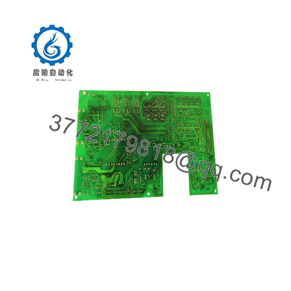
MD-B6027C
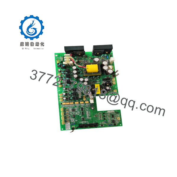
MD-B6027C
- Technical Pitfall & Survival Guide
- ❗ Firmware / ROM Chip Mismatch:
Swapping an MD- board between drives with different option stacks can cause startup faults or improper gate firing. I have seen engineers replace a board only to get an immediate drive fault because the socketed ROM chip contained logic for a different drive horsepower rating. Transfer your original socketed ICs or verify part numbers before powering up.
- ❗ DIP Switch / Jumper Misconfiguration:
Control boards rely on DIP switches and jumpers to set current feedback scaling, tachometer/encoder logic levels, and bus voltage thresholds. Always take a high-resolution photograph of the original board’s jumpers prior to removal and mirror them exactly on the replacement unit.
- ❗ DC Bus Capacitor & Gate Driver Discharges:
Never install or pull the MD- immediately after shutting off power to the drive. High-voltage DC bus capacitors can remain charged for several minutes. Measure DC bus voltage with a multimeter at the power terminals and confirm <50 V DC before disconnecting ribbon cables or power leads.
- ❗ Deteriorated Interconnect Ribbons:
Connectors on legacy Reliance systems can turn brittle from thermal cycling. Forcing flat ribbon cables into headers on the MD- can bend backplane pins or crack plastic housings. Inspect all multi-pin harness connectors and seat them carefully without excessive lateral force.
- ❗ Electrostatic Discharge (ESD):
Bare PCBs containing sensitive analog-to-digital converters and gate driver ICs can be destroyed by ungrounded handling. Always wear a grounded wrist strap attached to panel earth ground when removing the board from its anti-static bag and installing it into the chassis.
Keep these checks in mind and you’ll save yourself 90% of typical rework time.
- Installation & Configuration Guide
Stage 1: Pre-Installation Preparation (Est. Time: 15 mins)
- ⚠️ Safety First: Disconnect main 3-phase incoming power to the drive enclosure. Apply Lockout/Tagout (LOTO) tags. Wait at least 10 minutes for drive bus capacitors to drain. Verify zero voltage on power terminals using a calibrated multimeter.
- Tools Required: Grounded ESD wrist strap, needle-nose pliers, PH1/PH2 screwdrivers, multimeter, wire labels, and smartphone camera.
- Data Backup: Photograph all jumper settings, socketed IC positions, wire landings, and DIP switches on the existing board.
Stage 2: Removing the Old Board (Est. Time: 10 mins)
- Put on your grounded ESD wrist strap and connect it to enclosure ground.
- Label all multi-pin ribbon cables and discrete wire landings.
- Gently release locking clips on ribbon connectors and disconnect them straight back to avoid bending header pins.
- Remove chassis mounting screws or unlatch standoff clips, then carefully extract the MD- board from the drive assembly.
Stage 3: Installing the New Board (Est. Time: 15 mins)
- Remove the replacement MD- from its ESD bag on an ESD-safe workbench.
- Mirror all jumpers, DIP switches, and socketed option chips from the old board to the replacement board.
- Align the MD- with the chassis standoffs and secure all mounting hardware. Ensure grounding standoffs make clean contact with chassis metal.
- Reconnect all signal ribbons and terminal connectors. Verify every plug is fully latched.
Self-Checklist: [ ] Bus power verified zero, [ ] Jumpers match original, [ ] Harnesses fully seated, [ ] Ground screws tightened.
Stage 4: Power-On & Testing (Est. Time: 15 mins)
- Check for short circuits between control power supply terminals and ground using a multimeter.
- Apply control power first (if separate from main power) and verify logic LEDs light up normal boot sequences without fault indicators.
- Apply main power and test motor rotation at low speed, verifying current feedback and velocity feedback loops.
- Troubleshooting: If the drive trips on an overcurrent or gate fault immediately upon enable, recheck jumper settings for current scaling and ensure gate drive harness connectors are fully seated.
- Frequently Asked Questions (FAQ)
Q: Is the Reliance Electric MD- board hot-swappable?
A: No. Hot-swapping the MD- under power will damage the onboard logic ICs and can cause unpredictable gate firing to the drive power bridge, leading to short circuits. Always isolate main and control power before servicing.
Q: My board has the part number PISC-75A stamped on it. Is it identical to the MD-?
A: Yes. PISC-75A is the raw printed circuit board assembly number, while MD- is the Reliance system catalog number for the complete populated drive control base board. They refer to the same physical hardware assembly.
Q: Since this model is obsolete, what condition are these replacement units supplied in?
A: Because Reliance Electric no longer manufactures these legacy components, available stock is provided as Clean & Tested / Refurbished OEM stock. Units undergo full component-level inspection, electrolytic capacitor checks, and 24-hour dynamic load testing prior to sale.
Q: Will I lose drive tuning parameters when swapping out the MD-?
A: Basic analog adjustments (gain, offset, ramp times) set via onboard potentiometers or jumpers must be manually copied from your old board. Parameters stored in digital keypad memory modules or master controller cards are typically preserved, but hardware switch settings must be manually configured on the replacement board.
Q: Why are surplus or refurbished boards priced differently than original OEM list prices?
A: Surplus and refurbished industrial parts reflect secondary market availability for legacy control hardware. These components provide cost-effective replacements to keep critical plant production lines running without incurring the high downtime cost of a complete drive system migration.



