
 WhatsApp: +86 16626708626
 Email:
  Phone: +86 16626708626
Description
3. Key Technical Specifications
| Parameter | Specification / Value |
| Manufacturer | REO AG (REOTRON) |
| Part Number | 567LH-DP24 |
| Module Type | Industrial Thyristor Power Controller |
| Control Supply Voltage | 24 VDC (Auxiliary Logic Power) |
| Control Signal Input | 0 to 10 VDC / 4 to 20 mA Analog Setpoint |
| Operation Mode | Phase-Angle / Full-Wave Burst Firing Control |
| Cooling Method | Natural Convection / Integrated Heat Sink |
| Operating Temperature | 0°C to +45°C (+32°F to +113°F) |
| Mounting Style | DIN Rail / Backplate Panel Mount |
| Ingress Rating | IP20 Enclosure Protection |
| Packaging | Factory Anti-Static Shielded Box |
4. Product Introduction & Supply Chain Strategy
This product is a Brand New Surplus unit. It is not used, not pulled from a decommissioned plant, and not refurbished. All modules undergo rigorous quality verification to ensure OEM-level reliability. The REO REOTRON 567LH-DP24 Thyristor Power Controller regulates power delivery to resistive heating elements, infrared ovens, and vibratory feeding systems across automated manufacturing environments.
Securing this power controller as New Surplus is a critical supply-chain hedge against unplanned process halts. Because legacy REOTRON power regulators face long factory lead times or end-of-life status, a regulator failure on a production line can stop thermal processing or material feed lines for weeks. Refurbished thyristor units often contain heat-stressed power semiconductors, degraded snubber capacitors, and worn potentiometer pots that lead to thermal runaway or erratic current delivery. Purchasing genuine New Surplus guarantees factory-level firing accuracy and long-term service life while keeping your Total Cost of Ownership (TCO) below OEM list price.
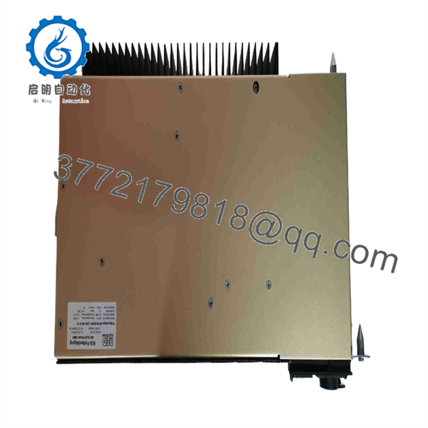
567LH-DP24
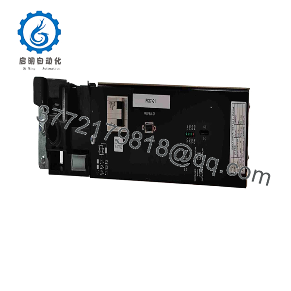
567LH-DP24
5. Installation & Configuration Guide
Stage 1: Pre-Installation (Prep & Safety)
- Disconnect main AC line power and 24 VDC control power feeds; enforce strict Lock-Out/Tag-Out (LOTO) procedures.
- Put on a grounded ESD wrist strap before touching control terminals or setpoint trimmers.
- Record wire labels, terminal assignments, and potentiometer positions on the original unit.
Stage 2: Removal
- Loosen terminal screw clamps and disconnect incoming AC power, load output cables, and 24 VDC control wires.
- Unbolt panel mounting screws or release the DIN-rail locking tab at the base of the unit.
- Remove the worn controller straight off the mounting panel.
Stage 3: Installation (Clone & Seat)
- Mount the replacement REOTRON 567LH-DP24 firmly onto the panel or DIN rail to ensure adequate vertical airflow across the heat sink.
- Replicate all DIP switch positions and potentiometer trimmer settings (zero/span adjustments) from the original module.
- Reattach power line wires, load leads, and 24 VDC control wiring to their corresponding screw terminals according to your wiring schematic.
Stage 4: Power-On & Testing
- Re-energize the 24 VDC auxiliary logic supply; verify the power status LED turns solid Green.
- Apply AC line voltage and feed a 0-10 VDC setpoint signal to the input terminals.
- Monitor the AC output voltage across the load using a true-RMS multimeter to confirm smooth phase-angle regulation corresponding to setpoint changes.
1.Pre-Installation & Setup:Line safety & terminal mapping.
Isolate main AC and 24 VDC power feeds using LOTO protocols. Put on an ESD wrist strap and document all terminal wiring and trimmer settings on the active controller.
2.Unit Removal:Power cable extraction.
Unscrew terminal block connections for line input, load output, and signal wires. Disengage the DIN-rail latch or remove panel bolts to extract the controller.
3.Hardware Mounting & Wiring:Trimmer alignment & mounting.
Snap the new REOTRON 567LH-DP24 onto the DIN rail, ensuring heat sink clearance. Set potentiometer trimmers to match the old unit and secure all wire terminations firmly.
4.Validation & Operational Test:Setpoint check & load test.
Power up the 24 VDC supply and AC line feed. Sweep the 0-10 VDC input signal and check true-RMS output voltage across the load to confirm linear power regulation.
6. Firmware/Software Versions & Upgrade Notes
- Signal Interface: The REOTRON 567LH-DP24 is an analog/hardware-driven thyristor controller and does not require software firmware updates.
- Control Rail Specs: Requires a stable 24 VDC (±10%) auxiliary control supply to drive internal firing circuits cleanly.
- Thermal Warning: Maintain a minimum 50 mm clearance above and below the heat sink fins. Inadequate cabinet ventilation will cause the internal thyristors to overheat, triggering thermal shutoff or premature power component failure.
7. Frequently Asked Questions (FAQ)
Q: Is the REO REOTRON 567LH-DP24 unit brand new or refurbished?
A: This controller is 100% Genuine New Surplus. It has never been deployed in an active plant installation, shows zero heat discoloration on its heat sink, and ships in protective anti-static packaging.
Q: Why should I choose New Surplus over a refurbished thyristor regulator?
A: Refurbished power controllers frequently suffer from thermal fatigue in internal SCR thyristor junctions and dried-out gate drive capacitors. Under heavy inductive or resistive loads, these degraded parts fail prematurely under thermal stress. New Surplus ensures original semiconductor integrity and factory-fresh component life.
Q: Does this unit support phase-angle firing control?
A: Yes. The 567LH- utilizes phase-angle control driven by a 0-10 VDC or 4-20 mA setpoint input, enabling smooth, proportional AC power regulation.
Q: Can I adjust the minimum and maximum output power on the unit?
A: Yes. Onboard potentiometer trimmers allow fine-tuning of zero-point offset and maximum output span to tailor power delivery to your specific load requirements.
Q: What warranty coverage applies to this module?
A: We back this REOTRON 567LH- module with a comprehensive 1-year replacement warranty, delivering total operational security compared to standard short-term used surplus terms.



