
 WhatsApp: +86 16626708626
 Email:
  Phone: +86 16626708626
Description
Key Technical Specifications
- Rated Output Current: 40 A continuous
- DC Bus Nominal Voltage: 700 V DC
- Mains Input: 3-phase, 380–480 V AC, 50/60 Hz
- Protection Rating: IP20
- Dimensions (H x W x D): 360 x 210 x 65 mm
- Weight: approx. 4.4 kg
- Cooling: Internal air blower
- Feedback: Supports absolute and incremental encoders
- Control Voltage: 24 V DC logic supply
- Firmware: ASE02 or ASE04 (confirm exact revision required at order time)
- Interface Options: Analog, SERCOS, or fieldbus module depending on sub-variant
- Series Classification: EcoDrive, DKC01.1/DKC01.3 family
Note: DKC01 covers several sub-variants (current ratings, interface cards, firmware). Confirm the exact nameplate suffix and firmware version against the OEM datasheet or the removed unit’s label before ordering.
Product Introduction
The Rexroth DKC01.1-040-7-FW is a digital AC servo drive controller in Bosch Rexroth’s Indramat EcoDrive line, built to regulate velocity, position, and torque for single or multi-axis motion control. It sits between the plant’s DC bus and the servo motor, converting command signals into phase-accurate current for pick-and-place, conveying, packaging, and CNC feed axes.
At 40 A continuous output and a 700 V DC bus rating, the DKC01.1 handles medium-to-large servo loads without derating. Its compact 360 x 210 x 65 mm footprint and internal blower cooling make it a practical fit for existing Indramat cabinet layouts, and its encoder flexibility (absolute or incremental) keeps it compatible with the motor feedback types already installed on most legacy EcoDrive lines.
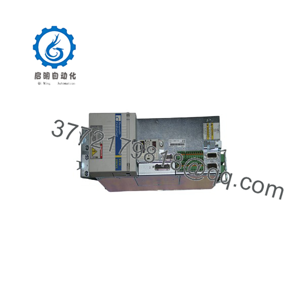
DKC01.1-040-7-FW
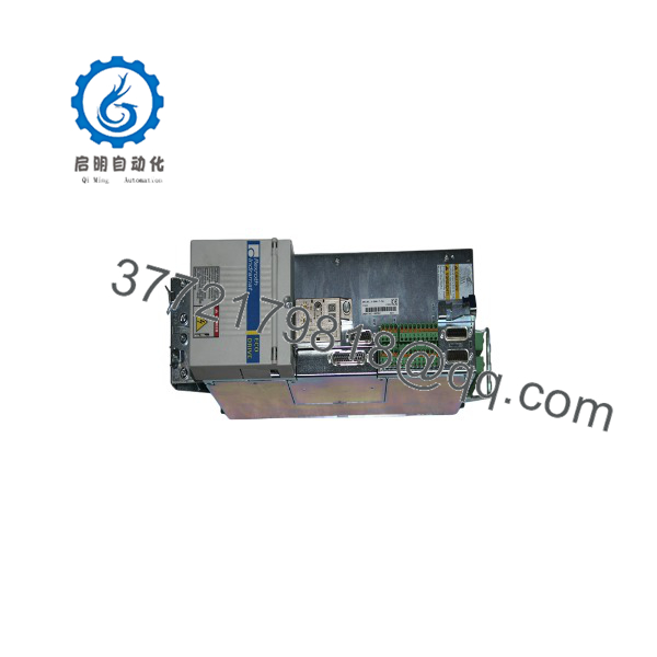
DKC01.1-040-7-FW
Installation & Configuration Guide
Stage 1: Pre-Installation Preparation (Est. 10 min)
⚠️ Safety First: Notify operations of planned downtime. Verify the axis is in a safe, de-energized state. Lock out/tag out the main disconnect. Wait a minimum of 5 minutes for DC bus capacitor discharge before opening the cabinet — the 700 V DC bus retains charge after power-down.
Tools Required: ESD wrist strap, PH1 screwdriver, digital multimeter, wire labels, smartphone for reference photos.
Data Backup: Document the current firmware version (ASE02 vs. ASE04) from the existing unit’s label. Photograph all terminal wiring, DIP switch positions, and any parameter/configuration disk or backup file if one exists. Record the assigned node/station address if the drive is on a bus.
Stage 2: Removing the Old Module (Est. 5 min)
- Remove the front cover/bezel.
- Label every wire before disconnecting — do not force spring or screw terminals.
- Release the DIN rail or rack locking mechanism and pull the unit straight out to avoid bending backplane pins.
- Inspect the backplane connector for bent pins, dust, or corrosion before proceeding.
⚠️ Note: Keep the old module on hand until the replacement is confirmed running correctly — it’s your fallback reference for wiring and configuration.
Stage 3: Installing the New Module (Est. 10 min)
- Ground yourself with the ESD strap. Confirm the replacement’s model suffix and firmware match what the application requires.
- Configuration Clone (Crucial): Set DIP switches and jumpers to match your photos exactly — pay particular attention to node address and bus termination.
- Seat the unit into the rack until it locks — listen for the click and confirm full engagement of the backplane connector.
- Reattach labeled wiring, torquing terminals to the manufacturer’s spec — don’t overtighten.
Self-Checklist: [ ] DIP switches match photo [ ] All wiring reattached and labeled [ ] Locking tabs fully engaged [ ] Firmware version confirmed
Stage 4: Power-On & Testing (Est. 5–10 min)
Pre-Power Check: Multimeter check across the 24 V control rail and DC bus terminals for shorts before applying power.
- Power the rack only — leave field devices (motor, brake) isolated for the first power-up if possible.
- Observe status LEDs. A steady green RUN state indicates a clean boot; a solid or blinking red ERR points to a fault.
- Connect programming/commissioning software and verify the drive reports the correct firmware version and node address.
- Restore backed-up axis parameters if the drive doesn’t already carry them.
- Dry-run the axis at low speed before returning to full production load.
⚠️ Troubleshooting Note: A solid red ERR LED or repeated communication timeout after swap is most often a firmware mismatch between the new unit and the master/PLC — verify the firmware revision (ASE02/ASE04) against what the old unit was running. If there’s no communication at all, check the interface cable, node address, and any termination resistor settings first.
Frequently Asked Questions (FAQ)
Is the DKC01.1-040-7-FW obsolete, and can I still get a genuine unit?
Yes, this is a legacy Indramat model — Bosch Rexroth has moved this line to inactive/surplus-only status for years now. Genuine units are still available through the surplus and refurbished market, but new-in-box factory stock isn’t coming from Rexroth. Ask your supplier directly whether the unit is new surplus or refurbished, and request serial number verification.
Will I lose my axis parameters when I swap the drive?
Not if you back them up first. On most setups, parameters live in the drive itself or on an external storage device from commissioning. Read and record the running configuration (or locate the original setup file) before pulling the old unit — otherwise you’re reconfiguring from scratch, which is a much longer job.
Can this drive be hot-swapped under power?
No. Don’t attempt it. The DC bus holds a 700 V charge that needs time to discharge, and pulling a live module risks damaging the backplane connector pins and anything else sharing that bus. De-energize, lock out, and wait for capacitor discharge every time.
What’s the difference between the .1 and .3 variants?
The .3 generally supports a broader interface set (including options for analog, stepper, and positioning control) and can run on either single/three-phase 230 V or 380–480 V three-phase input depending on configuration, while the .1 is the base version. Confirm the exact suffix on the nameplate — they aren’t universally interchangeable without checking firmware and interface compatibility.
Do I need to match the firmware exactly when I order a replacement?
Ideally, yes. There are two main firmware families for this series — ASE02 and ASE04 — and mixing revisions has caused real communication faults in the field, including drives that boot fine but throw comms timeouts against an older master. Check the label on your existing unit and request the matching firmware when you order.
Why is your price below Rexroth’s original list price?
Because this is surplus or refurbished stock, not new factory production — Rexroth stopped manufacturing this series some time ago. Pricing reflects the used/surplus market for a discontinued part, not a discount off current OEM pricing.
What’s your testing process before shipping?
Units go through inbound source verification, visual inspection for corrosion or rework marks, a power-on and communication handshake test, and I/O simulation before being packed in ESD-safe materials. Ask your supplier for their specific test report and photos — a reputable surplus seller should have no problem providing them.



