
 WhatsApp: +86 16626708626
 Email:
  Phone: +86 16626708626
Description
Key Technical Specifications
| Parameter | Specification |
| Model Code | FCS01.1E-W0011-A-04-NNBV |
| Rexroth Part Number (PN) | R911311065 |
| Rated Motor Power Output | 1.1 kW (1.5 HP) |
| Continuous Output Current | 3.6 A at 4 kHz switching frequency |
| Input Mains Power Voltage | 3-phase 380 V AC to 480 V AC (−15% / +10%) |
| Mains Input Frequency | 50 / 60 Hz (±5%) |
| Output Frequency Range | 0 to 400 Hz |
| Cooling Method | Air-cooled with internal fan (W0011 integrated cooling) |
| Braking Chopper | Integrated internal braking transistor |
| EMC Line Filter | Integrated Class A / Category C3 filter (A designation) |
| Degree of Protection | IP20 (Cabinet enclosure mounting required) |
| Operating Temperature | 0°C to +40°C (Up to +50°C with derating) |
| Unit Weight | 1.80 kg (3.97 lbs) |
Product Introduction & Supply Chain Strategy
The Bosch Rexroth FCS01.1E-W0011-A-04-NNBV (part number R911311065) is a compact, panel-mounted frequency converter designed for precise speed control of 3-phase AC induction motors in conveyor systems, pumps, fans, and general automated machinery. Featuring an integrated EMC filter and internal braking chopper, it delivers reliable V/f and vector-oriented motor control within a space-saving IP20 housing.
Procuring this drive as New Surplus secures vital operational continuity for mature automated lines without risking second-hand components. Refurbished VFDs frequently suffer from heat-stressed DC-bus electrolytic capacitors, fatigued power IGBT modules, or degraded gate drivers that cause unannounced overcurrent faults. Sourcing factory-fresh surplus stock ensures 100% rated lifespan, retains OEM insulation integrity, and provides a dependable 1-to-2 year operational warranty while eliminating costly downtime hazards.
Installation & Configuration Guide
Stage 1: Pre-Installation (Prep & Safety)
- Isolate the main branch supply circuit breaker and follow Lock-Out/Tag-Out (LOTO) procedures.
- Wait a minimum of 5 minutes after disconnecting power to allow internal DC-bus capacitors to fully discharge. Measure across DC+ and DC− power terminals to confirm voltage reads zero.
- Wear an ESD wrist strap connected to cabinet earth ground before handling control terminal connections.
- Record existing parameter sets and wire color designations from the original drive unit.
Stage 2: Removal
- Disconnect control terminal wiring plugs and main line/motor power cables from the drive terminal block.
- Unbolt the lower and upper mounting hardware securing the drive chassis to the control panel backplate.
- Lift the unit straight out from the panel guides, taking care not to place stress on adjacent cabling or ventilation channels.
Stage 3: Installation & Mounting
- Verify vertical clearance around the new unit (minimum 100 mm top and bottom) to ensure unimpeded air convection through the heatsink.
- Position the FCS01.1E-W0011-A-04-NNBV onto the mounting backplate and tighten all retention screws to specified torque settings.
- Reattach main input supply lines (L1, L2, L3) and motor output leads (U, V, W). Ensure protective earth (PE) connections are securely grounded.
Stage 4: Power-On & Testing
- Apply 3-phase 400 V AC power and check the digital operator panel for startup status.
- Verify motor nameplate data (Voltage, Current, Frequency, RPM) against the drive’s motor parameter group.
- Perform an uncoupled rotational test at low frequency (5 Hz) to verify motor spin direction and smooth current draw before running at full production speed.
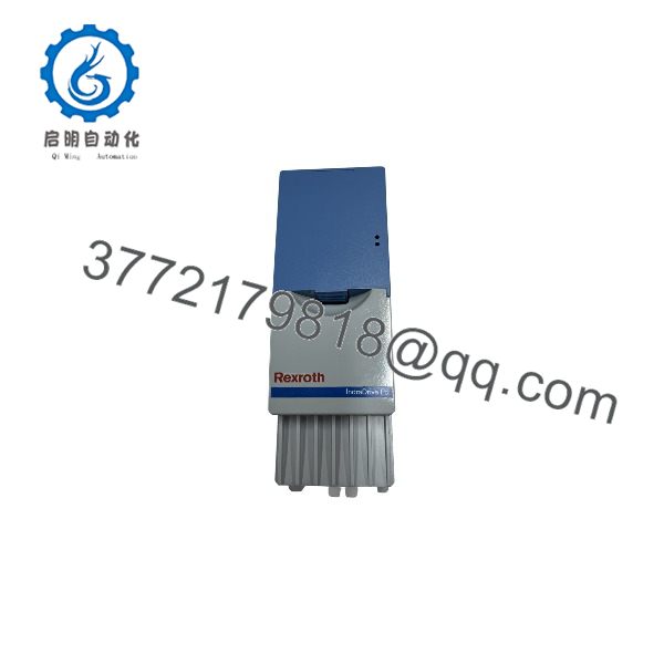
FCS01.1E-W0011-A-04-NNBV R911311065
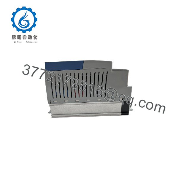
FCS01.1E-W0011-A-04-NNBV R911311065
Firmware/Software Versions & Upgrade Notes
- Parameter Backup Requirement: Always upload or record the parameter structure (specifically motor parameters, acceleration/deceleration ramps, and digital I/O mappings) from the old unit before swap-out.
- Digital Operator Keypad Transfer: The detachable operator keypad allows rapid offline transfer of stored parameter sets between units of the same power rating.
- Braking Resistor Configuration: If an external braking resistor is connected, ensure the internal braking chopper activation parameters are matched strictly to the external resistor’s ohmic rating to avoid thermal trips.
- Control Board Compatibility: Firmware variations between early and late production runs of the FCS series do not affect basic V/f motor control, but complex fieldbus option cards require verification against system master files.
Frequently Asked Questions (FAQ)
Q: How can I verify that this Rexroth FCS01.1E-W0011-A-04-NNBV drive is New Surplus?
Every unit is sourced directly from OEM spare parts reserves and factory overstock. Each drive arrives in original anti-static packaging with zero thermal wear on heatsink fins, zero mechanical marks on power terminals, and full verification of serial number R911311065.
Q: What does the type code FCS01.1E-W0011-A-04-NNBV signify?
- FCS01.1E: FCS Product Series, Generation 1.
- Air-cooled internal fan design with a 1.1 kW rating.
- A: Integrated Class A EMC filter.
- 04: 3-phase 380–480 V AC input rating.
- NNBV: Standard design configuration with integrated braking chopper.
Q: Is buying New Surplus better than purchasing a refurbished VFD?
Yes. Refurbished VFDs often rely on recycled power transistors and aged DC-bus capacitors that degrade during thermal cycling. A New Surplus drive gives you unused semiconductor junctions, factory insulation levels, and an expected 10-to-15 year operational service life.
Q: Can this drive be operated on a single-phase AC input supply?
No. The .1E–A-04-NNBV requires a balanced 3-phase 380–480 V AC supply. Running it on single-phase input will cause input phase-loss faults and severe DC-bus ripple under load.
Q: What warranty coverage applies to this drive?
All New Surplus Rexroth components come with a full 12-to-24 month functional replacement warranty, backing OEM-grade reliability without the lengthy lead times or inflated costs of legacy OEM factory builds.



