WhatsApp: +86 16626708626
 Email:
 Phone: +86 16626708626
Description
Key Technical Specifications
- Motor Frame Size: 065 (65 mm centering flange diameter)
- Motor Length Code: D (High-torque core package)
- Winding Code: 040 (Nominal rated speed: 4000 RPM)
- Continuous Torque (Standstill): 3.8 Nm
- Peak Torque: 14.5 Nm
- Nominal Current: 6.1 A
- Feedback System: Digital servo feedback with integrated encoder (N2L interface)
- Shaft Type: Keyed shaft according to DIN 6885-1 with shaft sealing ring
- Holding Brake: Integrated 24 V DC electromagnetic holding brake (PB option)
- Enclosure Rating: IP65 (dust-tight and protected against water jets)
- Operating Temperature: 0 to +40 °C
- Weight: 6.2 kg
Product Introduction
The Rexroth Indramat MDD065D-N-040-N2L-095PB1 is a high-dynamic permanent-magnet AC servo motor designed for demanding motion control applications. It operates in conjunction with Rexroth DIAX04, DKS, or ECODRIVE drive controllers across CNC machine tools, packaging lines, printing presses, and industrial robotics.
Engineered with high torque density, brushless design, and IP65 sealing, this motor delivers continuous positioning accuracy under high thermal and mechanical loads. The inclusion of a 24 V DC holding brake and a DIN keyed shaft makes it a direct fit for vertical axis control and high-inertia mechanical drivelines.
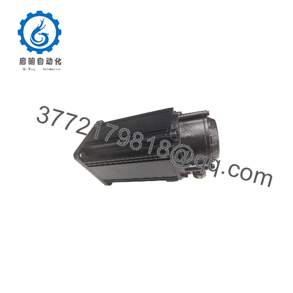
MDD065D-N-040-N2L-095PB1
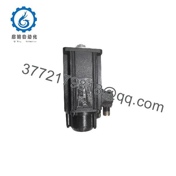
MDD065D-N-040-N2L-095PB1
Installation & Configuration Guide
Stage 1: Pre-Installation Preparation
- ⚠️ Safety First: Notify operations of machine downtime, execute Lock Out/Tag Out (LOTO) on drive amplifier power supplies, lock vertical axes mechanically to prevent gravity drops, and wait 5 minutes for drive DC bus capacitors to fully discharge.
- Tools Required: ESD grounding wrist strap, metric hex key set, torque wrench, dial indicator, Digital Multimeter (Fluke 115 or equivalent), reference camera.
- Data Backup: Document motor parameter codes from the drive display, check encoder feedback line termination, and photograph coupling alignment.
Stage 2: Removing the Old Motor
- Ensure the mechanical axis is firmly pinned or supported so it cannot drop under gravity once the holding brake is released.
- Label and disconnect power, brake, and feedback cables from the motor connectors. Do not yank on cables or twist connectors improperly.
- Loosen coupling clamp bolts and unbolt the motor mounting flange from the gearbox or machine frame.
- Carefully extract the motor without side-impacting the shaft or feedback connector housing.
- Self-Check: Confirm that connector pins on the wiring side are clean and unbent. Keep the old motor nearby for mechanical dimension verification.
Stage 3: Installing the New Motor
- Put on your ESD wrist strap. Verify that the full model code string on the nameplate matches
MDD065D-N-040-N2L-095PB1exactly. - Align the keyway, insert the shaft carefully into the flexible coupling, and seat the motor flange flush against the mounting surface.
- Torque flange mounting bolts in a cross-pattern to manufacturer specifications.
- Reattach feedback and power connectors, ensuring sealing rings are intact and bayonet latches/threaded rings are fully tightened to maintain IP65 rating.
- Self-Check: Rotate the motor shaft manually (with 24 V applied to release the holding brake) to check for binding before applying power.
Stage 4: Power-On & Testing
- Pre-Power Check: Measure winding-to-winding resistance and winding-to-ground insulation to confirm no damaged power lines or internal shorts exist.
- Power-On Steps:
- Energize the drive amplifier main control power while keeping the main AC bus disabled if possible.
- Verify that the drive reads the motor encoder data correctly without throwing feedback communication errors (
F218orF219). - Verify 24 V DC brake engagement/disengagement signals from the drive.
- Enable the drive at low speed and perform a jog routine to check direction and positioning stability.
- ⚠️ Troubleshooting Note: If the drive throws a motor feedback fault or position error on power-up, check the feedback cable latching, confirm pin alignment, and ensure the shielding ground is intact at the cabinet entry gland.
Frequently Asked Questions (FAQ)
Can this servo motor be replaced while the system is powered?
Honestly, unplugging or swapping a high-voltage servo motor while the drive amplifier is powered will cause heavy arcing on connector contacts, damage delicate feedback encoder electronics, and pose a severe electrical shock hazard. Always isolate and lock out main cabinet power before disconnecting motor leads.
Is this model obsolete, and is it genuinely new?
The MDD series is a mature legacy line from Rexroth Indramat, heavily deployed worldwide. Direct factory lead times can be extensive for older generations. Units designated as “New Original” or “New Surplus” are authentic factory-manufactured components that have never been commissioned on a machine, sourced from verified surplus reserves and canceled machine projects.
What is the direct replacement if this exact model is out of stock?
You must match every element of the model code: frame size (065), motor length (D), winding code (040), feedback type (N2L), and option codes (PB1 for holding brake + key shaft). Substituting a different winding code or feedback type will cause drive initialization failures in Rexroth DIAX04 / DKS controllers.
Will I need to program or tune the motor after installation?
Rexroth MDD motors store motor parameters and encoder alignment data directly in the onboard digital feedback interface. When connected to a compatible Rexroth drive, the drive automatically reads these parameters. You typically do not need to re-tune or re-parameterize the motor unless machine mechanical mass has changed.
Why is your price lower than OEM list price?
Surplus automation providers acquire excess stock from plant modernizations, machine builder inventories, and liquidations. By cutting out multi-tier distributor markups, we can provide maintenance engineers with immediate component availability at competitive pricing.
1.Verify Power Isolation:Prerequisite.
Turn off main drive cabinet breaker, apply LOTO, and verify zero voltage across drive DC bus terminals.
2.Secure Mechanical Load:5 min.
Block or lock vertical/heavy axes to prevent free-fall when the holding brake is disengaged.
3.Swap Hardware & Connectors:15 min.
Unbolt old motor, mount new unit, torque flange bolts in a cross pattern, and lock feedback/power connectors.
4.Commission & Jog Test:10 min.
Power on control power, check drive display for encoder health, and perform low-speed jog test.