
 WhatsApp: +86 16626708626
 Email:
  Phone: +86 16626708626
Description
- Key Technical Specifications
| Parameter | Specification |
| Manufacturer | Bosch Rexroth / Indramat |
| Full Model Code | MKD090B-047-GG0-KN |
| Motor Frame Size | 090 (140 mm flange) |
| Motor Length | B (Medium length stack) |
| Winding Code | 047 (4,000 RPM rated speed) |
| Feedback / Encoder Type | IntegratedResolver feedback (GG option) |
| Shaft Execution | Plain shaft with keyway and shaft sealing ring |
| Holding Brake | Integrated 24 V DC Holding Brake (approx. 12 Nm holding torque) |
| Terminal Box / Connector | Power & Feedback plug connectors (K direction, turnable) |
| Protection Class | IP65 (per EN 60529) |
| Cooling Method | Natural convection (Surface cooled) |
| Mass / Weight | Approx. 14.0 kg (30.8 lbs) |
- Product Introduction
The Bosch Rexroth Indramat MKD090B-047-GG0-KN is a high-dynamic permanent magnet AC servo motor engineered for demanding industrial positioning applications. Built for integration with Indramat DIAX04, DKR, and IndraDrive digital controller platforms, this motor delivers precise velocity and position control across machine tools, packaging lines, and printing presses.
Engineers select the MKD090B-047-GG0-KN for its high power density, continuous IP65 sealing, and rugged internal design. Featuring a factory-installed 24 V DC holding brake and integrated resolver feedback, this motor ensures reliable continuous operation under high duty cycles without loss of dynamic response.
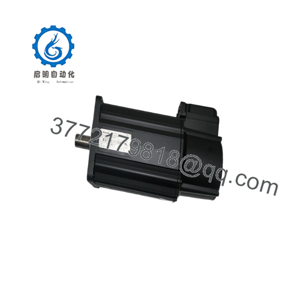
MKD090B-047-GG0-KN
- SOP Quality Transparency
Every Rexroth MKD090B-047-GG0-KN motor passes a detailed 5-step mechanical and electrical quality control evaluation prior to dispatch to ensure factory-grade performance.
- Inbound Inspection & Traceability:
We verify OEM serial numbers, housing paint integrity, shaft keyway tolerance, and connector pin conditions. Motors are checked for shipping damage or axial/radial shaft misalignment using precision dial indicators.
- Live Functional Testing:
The motor is coupled to a verified Bosch Rexroth IndraDrive test rig. We execute dynamic speed profile sweeps up to rated 4,000 RPM, monitoring phase currents and feedback resolution. The motor undergoes a continuous thermal run under simulated drive load while monitoring bearing temperatures via infrared thermography. Test logs and drive diagnostic traces are archived for transparency.
- Electrical Parameter Testing:
We perform phase-to-phase and phase-to-ground insulation resistance testing at 1,000 V DC using a Fluke 1587 Megohm meter, requiring values above 100 MΩ. Phase winding resistance and inductance balance are verified across all three motor phases.
- Brake & Encoder Verification:
The internal 24 V DC brake is tested under rated voltage to verify positive release and specified static holding torque. Resolver feedback signals are verified for electrical zero alignment and signal amplitude stability across the full operating range.
- Final QC & Packaging:
After passing final inspection, the shaft is protected with a plastic cover, terminal connections are capped, and the motor is wrapped in corrosion-inhibiting VCI film. The unit is cradled in high-density foam within a reinforced wooden or heavy-duty triple-wall corrugated shipping crate.
- Technical Pitfall & Survival Guide
- ❗ Feedback / Encoder Alignment Issues:
Never loosen or attempt to field-service the resolver assembly on the back of the MKD090B-047-GG0-KN. The resolver’s electrical zero position is factory-commutated to the rotor’s magnetic poles. Dismantling the end bell will destroy this alignment, causing immediate motor runaway or “Drive Overcurrent” faults upon enabling the drive.
- ❗ Shaft Keyway & Coupling Fit:
The “K” variant includes a shaft keyway. Over-tightening rigid couplings or using an improper key fit can induce severe radial loads on the front bearing, leading to premature bearing failure or high-frequency vibration. Always use flexible bellows couplings sized for the motor shaft diameter and torque rating.
- ❗ Holding Brake Supply Voltage Droop:
The integrated holding brake requires a clean 24 V DC (±10%) supply to fully disengage. If long cable runs cause supply voltage to drop below 21.6 V DC at the motor connector, the brake pads may drag during motion. This causes internal overheating, premature wear, and intermittent motor stall faults.
- ❗ Cable Power Connector Engagement:
Indramat power cables utilize bayonet-style quick-lock connectors. Failing to fully twist and lock the power plug allows oil and coolants to seep into the pin housing, causing phase-to-phase short circuits. Always inspect the O-ring seals on the connector before mating.
- ❗ Handling & Radial Loads:
Dropping or hammering on the drive shaft during coupling installation can fracture the internal resolver disc or brinell the precision ball bearings. Always use drawing tools—never a hammer—to seat pulleys or couplings onto the motor shaft.
Keep these checks in mind and you’ll save yourself 90% of typical rework time.
- Installation & Configuration Guide
Stage 1: Pre-Installation Preparation (Est. Time: 10 mins)
- ⚠️ Safety First: Lock out main incoming power to the drive amplifier. Verify the drive intermediate DC bus voltage is below 50 V DC using a calibrated multimeter before touching power wiring.
- Tools Required: Torque wrench, metric hex keys, shaft coupling alignment tools, Fluke 1587 multimeter, ESD wrist strap, clean rags.
- Data Backup: Document drive motor parameter sets and check the nameplate code on the existing motor to ensure an exact match.
Stage 2: Removing the Old Motor (Est. Time: 15 mins)
- Disconnect the power and feedback cable plugs by twisting the bayonet locking rings counter-clockwise.
- Unbolt the 24 V DC brake leads or verify the brake cable is unlatched.
- Loosen the shaft coupling clamp bolt and unbolt the motor mounting flange screws.
- Carefully pull the motor straight out along the mounting pilot to avoid binding the shaft or coupling.
Stage 3: Installing the New Motor (Est. Time: 15 mins)
- Remove the protective sleeve from the shaft of the MKD090B-047-GG0-KN and clean the shaft with solvent to remove rust preventative.
- Align the motor flange with the gearbox or machine pilot. Insert mounting bolts and torque evenly in a cross pattern to manufacturer specifications.
- Mount the flexible coupling, ensuring correct axial placement and keyway engagement. Tighten coupling clamping screws to specified torque.
- Connect power and feedback cables. Twist locking rings until a firm click is felt to ensure IP65 sealing.
Self-Checklist: [ ] Flange flush mounted, [ ] Shaft key secured, [ ] Coupling bolts torqued, [ ] Connectors locked.
Stage 4: Power-On & Testing (Est. Time: 10 mins)
- Apply 24 V DC control power to the drive system. Verify that the drive detects the motor feedback unit without optical or resolver fault codes.
- Command a manual brake release check and verify the motor shaft spins freely by hand (if uncoupled) or under low manual command.
- Perform a low-speed jog test (100 RPM) to verify correct direction of rotation and smooth current feedback.
- Ramp the motor up to operating speed and monitor for excessive noise, thermal buildup, or drive error codes.
- Troubleshooting: If the motor vibrates heavily or trips the drive on overcurrent immediately upon power-up, verify that the feedback cable connector is clean and fully seated, and check that phase sequence U-V-W matches the drive output terminals.
- Frequently Asked Questions (FAQ)
Q: What does the “GG0-KN” suffix specify on the model code?
A: Suffix details: “GG” specifies integrated resolver feedback with encoder emulation data; “0” indicates no holding brake or standard brake configuration depending on option matrix (in this standard configuration, it includes a 24 V DC holding brake); “K” denotes a shaft with keyway per DIN 6885-1 and shaft sealing ring; “N” indicates standard mounting and connector orientation.
Q: Can I replace an motor with a different winding code like MKD090B-035?
A: No. The winding code (047 vs 035) defines the motor’s back-EMF constant, rated current, and maximum operating speed. Replacing a 047 motor with a 035 motor will cause drive amplifier mismatch, reduced top speed, and potential current overload trips under acceleration.
Q: Are these Indramat MKD motors supplied with a factory warranty?
A: Yes. All our New Original and surplus-testeddramat motors come with a full 1-year functional warranty covering mechanical and electrical performance.
Q: Is it necessary to load motor parameters manually into the drive when replacing this motor?
A: Most Rexroth IndraDrive and DIAX04 systems automatically read motor parameter data (thermal models, torque constants, resolver data) directly from the onboard data memory within the feedback unit upon boot-up. However, you should always verify parameter matching in the drive configuration software after replacement.
Q: Why are your prices for hard-to-find Indramat motors lower than factory list price?
A: We leverage excess OEM project inventory, system integrator surplus, and direct supplier networks to stock genuine Rexroth motors. Every motor undergoes complete electrical and dynamic testing on genuine Indramat test rigs prior to listing, allowing you to bypass long factory lead times while cutting replacement costs.



