WhatsApp: +86 16626708626
 Email:
 Phone: +86 16626708626
Description
Key Technical Specifications
| Parameter | Value |
|---|---|
| Product type | 8-axis motion control board, ISA-bus format, PC-hosted |
| Controlled axes | 8 axes |
| Host interface | ISA (Industry Standard Architecture) PC bus slot |
| Control architecture | Closed-loop point-to-point and coordinated multi-axis motion |
| Servo interface | Analog command outputs to external servo drives via axis connectors |
| Feedback inputs | Encoder inputs, per-axis 15-pin high-density D connectors (family-standard) |
| Additional I/O | AUX and general-purpose DC inputs/outputs (family-standard connector set) |
| Board reference | PCB markings reported as “PCB-I-E-233=2M11” on some units — revision varies |
| Programming environment | MMC software toolchain (family-standard) |
| Board format | Full-length plug-in card, ESD-sensitive, board-level (IP20 equivalent) |
| Operating environment | Industrial control enclosure; host PC backplane |
| Compatibility | MMC motion platforms with matching servo drive and encoder sets |
⚠️ Transparency note: OEM documentation for this exact part number is scarce on the open market. The MMC-family Hardware Manual (Giddings & Lewis Controls, P/N 108-31050-00, publicly hosted under the Kollmorgen document library) documents the family architecture: per-axis 15-pin high-density D connectors, encoder input theory of operation, AUX/axis DC inputs, chassis-grounded connector shells, and the onboard MMC battery replacement procedure. Verify the board revision, PCB silkscreen markings, connector pinout, and host software pairing against your installed card before ordering. We photograph the exact board — including PCB revision silkscreen — before shipping so you can match your unit precisely.
Product Introduction
The Rockwell MMC-BDPV81INA (8B17CC0056A) is an 8-axis ISA-bus motion control board from the legacy MMC platform — the motion hardware inside a large installed base of machine tools, packaging machinery, and specialty automation, much of it still running production shifts today. Eight servo axes per board: analog commands out to the drives, encoder feedback back through individual 15-pin axis connectors, and machine I/O through the AUX and general-purpose interfaces.
Two practical facts drive every purchase of this board. First, it’s ISA-bus hardware — the host PC it lives in is as obsolete as the board itself, so a dead card usually means hunting legacy spares, not a retrofit decision made calmly. Second, it’s a single point of failure with no factory replacement path. A verified, tested spare on the shelf turns a dead machine into a 30-minute card swap. That’s what we supply, with full traceability on condition and revision.
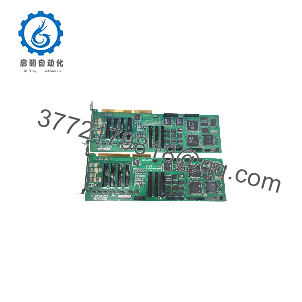
MMC-BDPV81INA (8B17CC0056A
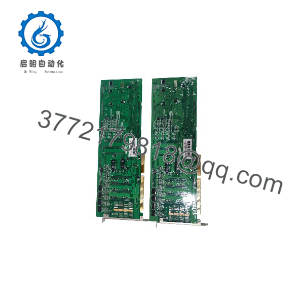
MMC-BDPV81INA (8B17CC0056A
Installation & Configuration Guide
Stage 1: Pre-Installation Preparation (~20 min)
- ⚠️ Safety First: Notify operations and schedule the downtime. Drive all axes to a safe position — every axis drops the moment the host PC loses power, so block any gravity-loaded or overhauling axis mechanically before you touch the PC. Lock out/tag out the host PC and the machine control cabinet. Wait 5 minutes for capacitor discharge, then verify with a multimeter before opening either enclosure.
- Tools Required: Grounded ESD wrist strap, ESD mat, multimeter (Fluke 115 or equivalent), small flathead and PH1 screwdrivers, cable labels, smartphone for photos.
- Data Backup: Export motion programs, axis parameter files, and machine configuration from the host software. Photograph the board fully wired from two angles: bracket screw, every cable on every axis connector (they’re similar 15-pin D connectors — label all of them), and every visible DIP switch and jumper. Configuration lives partly on this board; the photos are your restoration reference.
- Revision Documentation: Record the host software version and the board’s PCB silkscreen revision (e.g., “PCB-I-E-233=2M11”-style markings). On MMC-family hardware, board revision versus host software version is the number-one swap failure mode.
Stage 2: Removing the Old Board (~15 min)
- ESD strap on, mat down. This is bare-board hardware — a static zap kills it before you ever power up.
- Photograph the wired board. Label each cable at its connector.
- Remove the retaining bracket screw at the rear of the PC chassis.
- Disconnect axis, feedback, AUX, and I/O cables by their connectors — never by the cable. Note the connector shells are tied to chassis ground through the power connector; keep the ground path intact when you reinstall.
- Pull the board straight out of the ISA slot with even pressure. ISA edge connectors are long and friction-heavy — work it out gently side to side along the slot axis, never by prying against components. Into an ESD bag immediately.
- Inspect the slot contacts for dust and corrosion; clean with dry air. ISA slots in 20-year-old industrial PCs collect more grime than you’d expect.
- ⚠️ Keep the old board until the replacement runs clean. Its jumper positions and revision silkscreen are your reference.
Stage 3: Installing the New Board (~15 min)
- ESD strap on. Verify the board markings match MMC-BDPV81INA / 8B17CC0056A; compare the PCB revision silkscreen against your photos.
- Configuration clone: Mirror every DIP switch and jumper position from the photo of the old board. I’ve debugged a machine that ran every axis at half speed for two days because one encoder-format jumper didn’t match. Take the picture. Match it exactly.
- Align the ISA edge connector with the slot and press in evenly with firm pressure until fully seated. Verify by sight that the edge contacts have disappeared into the slot — partial ISA seating is common and produces intermittent faults.
- Secure the bracket screw. Reconnect all labeled cables, verifying each against the photos.
- Self-Checklist: [ ] Revision matches, [ ] Jumpers/DIPs mirror photo, [ ] Board fully seated in ISA slot, [ ] All cables on correct connectors, [ ] Chassis ground path intact, [ ] Cabinet cover off until first power-up test.
Stage 4: Power-On & Testing (~20 min)
- Pre-power check: meter the machine-side 24 V and axis command lines for shorts to ground before re-energizing.
- Power up the host PC only — servo drives off. Confirm the host software recognizes the motion hardware with no board-level fault reported.
- Restore drive power one axis group at a time. Enable the first axis only.
- Jog the first axis at 10% or less. Verify direction, listen to the drive, check for following errors in the host diagnostics.
- Repeat per axis, then run a slow coordinated multi-axis move. Restore the full machine program only after every axis passes individual and coordinated checks.
- ⚠️ Troubleshooting Note: A communication or board-not-found error at power-up means the board isn’t fully seated or the host software doesn’t match the board revision — reseat first, then verify versions. One backward-running axis means command or encoder polarity differs from the old board’s configuration — fix it in configuration, never by hot-swapping wires. Following errors across all axes point to an encoder-format jumper mismatch: go back to your photos. And if the board loses its configuration after a power cycle, check the onboard battery — the MMC family Hardware Manual documents the battery replacement procedure.
Frequently Asked Questions (FAQ)
Q1: This part has two numbers — MMC-BDPV81INA and 8B17CC0056A. Which one am I getting, and is it genuinely the same part?
They’re cross-references for the same 8-axis ISA motion control board — machine builders and surplus channels use the two numbers interchangeably. What matters more than the part number is the PCB revision silkscreen, which varies between production runs and interacts with your host software version. We photograph the exact board you’ll receive — including the PCB markings — before shipping, so you can verify against your installed unit. If your machine documentation demands a specific revision, tell us before ordering and we’ll match it or tell you honestly that we can’t.
Q2: Is this model obsolete, and is what you’re selling actually new?
Yes — the MMC platform is long discontinued with no factory replacement path. Our stock is New Original / New Surplus where available: genuine production, never placed in service, with factory packaging when it survives. Given the platform’s age, some units are honestly labeled Refurbished (tested) — stated as such, never blended into new-surplus listings. Either way, we verify part markings and revision silkscreens, screen for counterfeits, and document the condition of the onboard battery and any NVRAM component. Ask, and we’ll tell you exactly what you’re getting.
Q3: Can I hot-swap this board under power?
No. It’s a board-level ISA card, not rack hot-swap hardware. Pulling it live risks the board, the host PC’s slot, and the servo wiring downstream — plus every axis drops the instant the board loses power anyway. Power down both the host and the drive cabinet, verify zero volts, block gravity-loaded axes, then pull it. Ten extra minutes to protect a board this hard to replace.
Q4: What’s the direct replacement if this exact unit is out of stock?
Within the MMC family there are other 8-axis boards and different axis-count variants, but variants differ in connector count, pinout, and revision compatibility — none of them is a guaranteed drop-in. There is no current-production equivalent on an ISA bus; the modern migration path is a full motion platform retrofit (current PC-based or PLC-integrated motion, new drives, new feedback, and a rewrite of the motion programs). Most plants with this hardware keep a tested spare on the shelf instead. Send us a photo of your installed board’s markings and we’ll confirm before you order.
Q5: Will I lose my motion programs when I swap the board?
Programs and axis parameters live in the host PC’s storage — back those up in the software first. But jumper settings, encoder formats, and in some configurations the board’s stored setup live physically on the board, and the MMC family carries an onboard battery for retention. Photograph every jumper and connector, mirror the configuration exactly, and check the battery state on the replacement board before you trust it for production. Skip this and you’re reverse-engineering your own machine at 2 AM.
Q6: Why is your price lower than the original list price?
The OEM stopped making this hardware years ago. Our stock comes from machine builder spares programs, plant liquidations, and factory overruns. We’re not an authorized distributor, and we state that plainly: the 12-month warranty is ours, not the OEM’s. You’re trading factory support — which no longer exists for this platform — for price and availability. For a legacy machine still making good parts, that trade is easy math.
Q7: What quality checks do you run before shipping?
Every unit passes inbound inspection (part marking and PCB revision verification, counterfeit screening, visual audit of board condition and connectors), then a bench test: power-up self-test, host recognition handshake, and axis/AUX connector continuity verification where the test fixture allows. Because this family carries an onboard battery for configuration retention, we specifically test and document the battery and NVRAM state — a dead backup battery on a legacy board is a classic hidden failure that shows up a week after installation. Results are logged in a signed Test Report; the board ships in an ESD-shielded bag with a QC Passed label and date. Test photos and revision markings are available on request. We won’t claim it’s failure-proof — we’ll tell you exactly what we verified.