
 WhatsApp: +86 16626708626
 Email:
  Phone: +86 16626708626
Description
Key Technical Specifications
| Parameter | Specification |
|---|---|
| Manufacturer | Rolls-Royce Marine AS |
| Product Line | Tenfjord Steering Gears |
| Model | 5880-PC1025 |
| Hardware Revision | Rev B |
| Manufacturer P/N | 5801-R105-00 |
| Alternative P/N | 5880PC1025 |
| Arrangement No. | 5880-1025 Rev. B |
| Board Type | Printed circuit board |
| Primary Function | Rudder indicator amplifier |
| System Application | Marine steering gear |
| System Configuration | Tenfjord steering gear architecture |
| Output Role | Drives/conditions rudder-angle indication signals |
| Supply Marking | ±12 V DC output rails and 18–36 V DC main supply are reported for Rev B |
| PCB Marking | 94V-0 Elprint |
| Related Identification | 446057 / NC 62927 markings reported on certain units |
The strongest available part-level references identify 5880-PC1025 as a Tenfjord steering-gear PCB, Rev B, with manufacturer number 5801-R105-00. One technical catalog also reports 18–36 V DC main supply and ±12 V DC rails on the board. Exact terminal assignments, calibration values, and signal ranges should be confirmed against the vessel-specific steering gear documentation before installation.
Product Introduction
The Rolls-Royce Marine 5880-PC1025 is a Rev B printed circuit board used in Tenfjord marine steering gear systems. Its documented application is as a rudder indicator amplifier, processing feedback from the steering gear and providing the appropriate signal path for rudder-angle indication equipment.
This is a legacy marine automation component where exact hardware revision and system compatibility matter more than generic electrical similarity. The documented identification includes 5801-R105-00, 5880-1025 Rev. B, and Tenfjord steering-gear service designation. Do not substitute another 5880-series PCB solely because the board dimensions or connector arrangement appear similar.
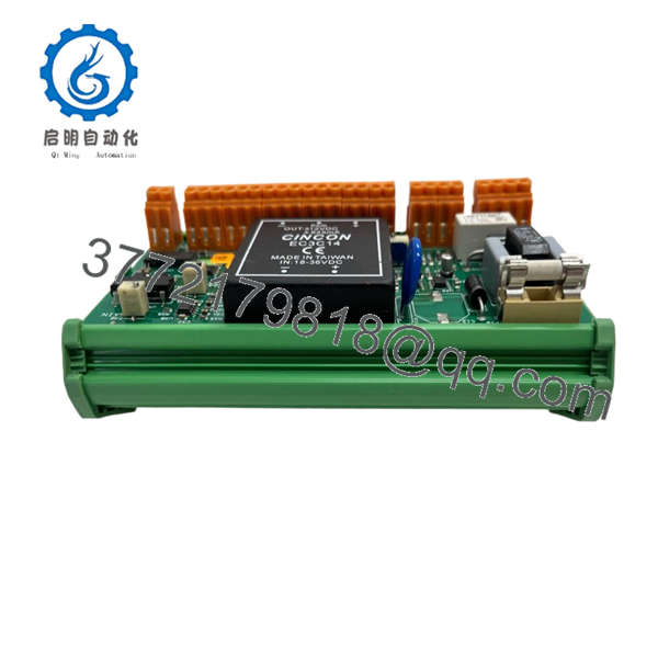
5880-PC1025
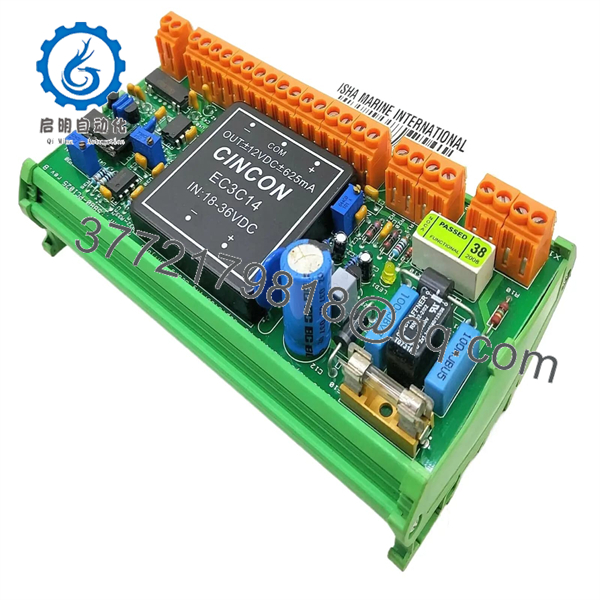
5880-PC1025
Installation & Configuration Guide
Stage 1 — Pre-Installation Preparation
Estimated time: 20–30 minutes
- Notify vessel operations and place the steering gear system in the approved maintenance state.
- Follow the vessel’s lockout/tagout (LOTO) procedure and isolate the applicable steering-control power.
- Allow at least 5 minutes for stored electrical energy to dissipate before touching the PCB.
- Wear an ESD wrist strap and use an antistatic work surface.
- Prepare a PH1 screwdriver, multimeter, wire labels, camera/phone, and the applicable Tenfjord steering-gear drawings.
- Record the existing board’s:
- Model number
- Revision
- Part number
- Board markings
- Connector positions
- Jumper or configuration positions
- Photograph the installed wiring before disconnecting anything.
⚠️ Critical: Verify that the replacement is 5880-PC1025 Rev B where the existing system requires Rev B. Current marine spare-parts records specifically identify this version as Art. No. 5880-1025 Rev. B / 5801-R105-00.
Stage 2 — Removing the Old Module
Estimated time: 15–25 minutes
- Confirm the steering gear control cabinet is electrically isolated.
- Remove the applicable front cover or PCB retaining hardware.
- Label each connector or wire before removal.
- Disconnect the board without pulling on individual conductors.
- Release the PCB retaining mechanism or rack clips.
- Pull the card straight out, keeping the board parallel to the card guides.
- Inspect the backplane, connector contacts, and surrounding wiring for:
- Corrosion
- Salt contamination
- Burn marks
- Loose terminals
- Bent contacts
- Moisture ingress
- Retain the removed board until the replacement has passed functional testing.
⚠️ Marine steering equipment can develop connector oxidation and contamination even when the PCB itself appears visually clean. Do not assume a replacement PCB will correct a fault caused by the cabinet wiring or feedback sensor.
Stage 3 — Installing the New Module
Estimated time: 20–30 minutes
- Compare the replacement board against the removed unit.
- Confirm:
- 5880-PC1025
- Rev B
- 5801-R105-00, where applicable
- Connector orientation
- Board markings
- Check jumper, selector, or configuration positions against the original board and approved system documentation.
- Inspect the card-edge connector for contamination or mechanical damage.
- Use ESD protection while handling the PCB.
- Insert the board carefully into the correct rack or enclosure slot.
- Seat the PCB fully without excessive force.
- Reconnect wiring according to the photographs and vessel drawings.
- Perform a point-to-point wiring check before energization.
⚠️ Do not assume pin compatibility from the model number alone. The 5880-PC1025 belongs to a Tenfjord steering-gear architecture and should be matched to the specific steering gear configuration.
Stage 4 — Power-On & Testing
Estimated time: 30–60 minutes, excluding sea trial
- With power still isolated, use a multimeter to check for unintended shorts on the applicable DC supply rails.
- Energize the steering control system according to the vessel’s approved startup procedure.
- Check PCB and system status indications.
- Verify the rudder feedback signal at the steering controller.
- Compare the bridge rudder-angle indication against the actual rudder position.
- Move the steering gear through the approved test range at low risk and controlled speed.
- Check for:
- Correct rudder direction
- Stable indication
- No signal dropout
- No abnormal oscillation
- Correct center/neutral indication
- Perform the manufacturer’s or vessel operator’s required steering gear alarm and feedback checks.
- Record the replacement board’s serial/traceability information and final test results.
⚠️ Do not perform an operational steering test with personnel or equipment exposed to uncontrolled rudder movement. The steering gear manufacturer’s procedures and vessel safety procedures take precedence.
For a legacy PCB, a useful replacement test record should include incoming visual inspection, connector condition, power-rail measurements, feedback simulation where test equipment permits, and final steering indication verification. Test photographs or videos can be retained as maintenance evidence when available.
Frequently Asked Questions (FAQ)
1. What is the Rolls-Royce 5880-?
The 5880- is a Tenfjord steering gear printed circuit board used as a rudder indicator amplifier within Rolls-Royce Marine steering gear equipment.
2. What is the correct part number associated with 5880-?
Marine spare-parts records identify V.Nr 5801-R105-00 as the manufacturer’s part number. The board is also identified as Art. No. 5880-1025 Rev. B.
3. Is 5880- obsolete?
It is a legacy marine control PCB, and current secondary-market listings describe it as obsolete or offer it as used/new-surplus stock. Condition varies considerably by supplier, so the actual board revision and condition should be confirmed before ordering.
4. Can another 5880-series PCB replace 5880-?
Not automatically. Other 5880-series boards, including 5880-PC1019, PC1024, PC1026, and PC1028, have different documented functions or configurations. A replacement should be selected by exact part number, revision, steering gear architecture, and wiring configuration, not by series number alone.
5. Can the PCB be replaced while the steering gear is energized?
No. The steering gear control power should be isolated under the vessel’s approved maintenance and LOTO procedure before removing or installing the PCB. This also reduces the risk of transient damage to feedback and control circuitry.
6. What condition is available for 5880-?
Secondary-market sources currently show used, refurbished, and new-surplus/new descriptions. One marine spare-parts listing specifically records a used Rev B unit, while other suppliers advertise new-surplus or new units. Confirm photographs, revision markings, test status, and warranty terms with the supplier before purchase.
7. What should be verified before ordering?
At minimum, provide the supplier with the existing 5880- identification, Rev B marking, 5801- part number, vessel/steering gear configuration, and clear PCB photographs. This is particularly important for legacy Tenfjord systems where visually similar boards may perform different functions.



