
 WhatsApp: +86 16626708626
 Email:
  Phone: +86 16626708626
Description
Key Technical Specifications
| Parameter | Specification |
|---|---|
| Model | H1111.0103 |
| Rolls-Royce P/N | 75669 |
| Reported PIC Code | Rev. 2.2 |
| Product Type | Marine controller / processing module |
| System Platform | Rolls-Royce Marine CCS / Damatic-related architecture |
| Supply Voltage | 24 VDC nominal |
| Processor | Reported 300 MHz RISC architecture |
| Ethernet | Reported dual Ethernet, 10/100 Mbps |
| Serial Interface | RS-485 |
| Fieldbus | CAN bus |
| Application | Vessel automation, propulsion and machinery control |
| Lifecycle | Legacy / limited availability |
The 24 VDC, 300 MHz processor, Ethernet, RS-485, and CAN-bus specifications appear across multiple secondary-market records, but I did not locate an authoritative current Rolls-Royce datasheet confirming every hardware revision or connector assignment. Treat these values as procurement-reference specifications rather than a substitute for the OEM documentation.
Product Introduction
The Rolls-Royce H1111.0103 is a specialized marine automation controller associated with Rolls-Royce vessel control architectures. Secondary industrial records identify it as part number 75669, with a reported 24 VDC supply and 300 MHz processor.
The module is intended for real-time marine automation rather than generic PLC applications. Its reported Ethernet, CAN bus, and RS-485 interfaces allow it to participate in distributed propulsion, machinery, and vessel-control networks.
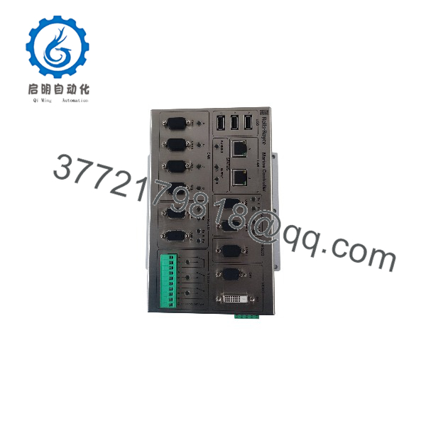
H1111.0103
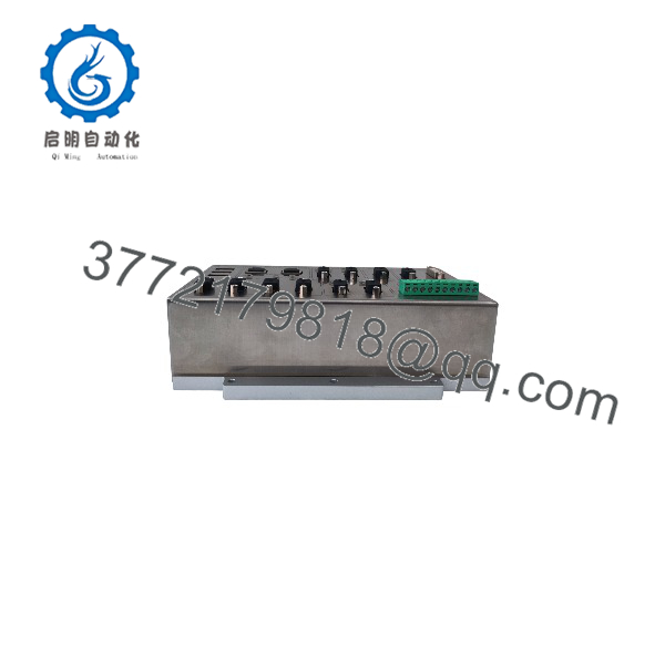
H1111.0103
Installation & Configuration Guide
Step 1 — Confirm the Existing Hardware
Before removing the failed controller, record:
- H1111.0103 model number
- Part number 75669
- PIC revision and hardware revision
- Serial number
- Connector arrangement
- Existing cable locations
- Controller rack or cabinet position
Take photographs of the complete front, rear, connectors, and adjacent modules.
Warning: Do not order solely from the H1111.0103 designation if the replacement will be installed in a safety- or propulsion-related control system. Secondary sources contain conflicting descriptions of this part, so the physical unit and installed system documentation should take precedence.
Step 2 — Back Up Configuration
Before replacement, preserve the existing controller configuration whenever the system permits it.
Record:
- Application software or firmware revision.
- PIC/hardware revision.
- Network addressing.
- CAN-bus configuration.
- RS-485 communication settings.
- Controller redundancy or synchronization parameters.
- Vessel-specific control database.
Do not assume that a replacement controller will automatically contain the vessel’s application program.
Step 3 — Isolate Power
Shut down the appropriate control-system power source according to the vessel’s maintenance procedure.
Verify that the controller is electrically isolated before disconnecting cables.
Use appropriate ESD protection when handling the controller. Label every cable before removal; marine control cabinets can contain multiple visually similar communication connections.
Step 4 — Remove the Existing Controller
Disconnect the communication and power connections without pulling on the cable conductors.
Inspect:
- Connector pins
- Cable shields
- Grounding points
- Terminal condition
- Corrosion or salt contamination
- Signs of overheating
- Mechanical damage
If corrosion is present, replacing the controller alone may not resolve the original fault.
Step 5 — Install the Replacement
Install the H1111.0103 in the same mechanical position and reconnect each cable according to the recorded connection map.
Verify the supply voltage before energizing. The commonly reported nominal supply is 24 VDC; do not apply power based solely on connector appearance.
Step 6 — Commission the Controller
After power-up:
- Confirm normal controller startup.
- Check the installed firmware/PIC revision.
- Verify network communication.
- Confirm CAN-bus communication.
- Verify RS-485 communication where used.
- Restore the approved application configuration.
- Check controller diagnostics and alarms.
- Confirm communication with associated propulsion and machinery controllers.
- Perform functional testing under the vessel’s approved commissioning procedure.
For propulsion or other safety-critical functions, a successful boot and network connection are not sufficient acceptance criteria. The application logic, I/O mapping, communication behavior, and system-level control functions must also be verified.
FAQ
Is H1111.0103 a standard PLC?
No. Available records identify it as a specialized Rolls-Royce Marine controller/processing module associated with vessel automation architectures. It should not be treated as a generic PLC simply because it performs control-processing functions.
What is the Rolls-Royce part number for .0103?
Secondary industrial records consistently associate with Rolls-Royce part number 75669. Some listings also report PIC revision 2.2. Verify the marking on the physical controller before purchasing.
Does .0103 operate on 24 VDC?
Yes, 24 VDC nominal operation is repeatedly reported for this model. However, the exact allowable voltage range and redundancy arrangement should be confirmed from the installed system documentation before energizing a replacement.
Can another 24 VDC PLC directly replace .0103?
Not on voltage compatibility alone. Firmware, application configuration, communications, connector pinout, CAN-bus behavior, and vessel-specific control logic must all match. A generic Siemens, Allen-Bradley, or other PLC should not be considered a drop-in replacement.
Is .0103 obsolete?
It appears to be a legacy, limited-availability controller in current secondary-market listings. This does not by itself establish an official Rolls-Royce lifecycle status, so an OEM lifecycle notice or vessel documentation should be used when formal obsolescence confirmation is required.
What should be checked when buying a replacement?
At minimum, match:
- .0103
- Part number 75669
- PIC/hardware revision
- Firmware/application compatibility
- Connector configuration
- Physical mounting arrangement
- Ethernet/CAN/RS-485 requirements
- Condition and test documentation
For a used or surplus unit, request clear photographs of the nameplate and connectors plus evidence of functional testing.



